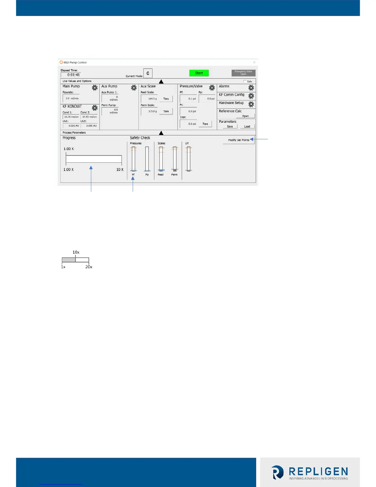
Figure 1B: Overview view of Pump Control
Main Pump: Set and display pump drive's flow rate, pump direction, current Pump Mode, and Ramp
Rate.
Auxiliary Pump 1: Display Auxiliary Pump 1 flow rate. Can only set Auxiliary Pump 1 flow rate in
Manual mode.
Auxiliary Pump 2: Set and display Auxiliary Pump 2 flow rate. Can not be set in C/D/D/C and CF/D/C
Mode, as the Auxiliary Pump 2 operates as a Diafiltration Pump in those two modes.
Pressure/Valve: Set and display target psi/bar and also set Auto or Manual mode. Can manually set
pinch distance in Manual Mode. Dialog box also displays current pressure readings from pressure
transducers
. Pressure sensors can also be tared.
Alarms: Set and display alarms and stops.
Safe Checkboxes: Checking the “safe” checkbox disables changing values.
Reference Calculator: The Reference Calculator allows the user to run calculations for Pump Modes
to estimate the volumes of solution that will be moved through the flowpath from the beginning to
end of a Pump Mode application.
process bar fills up to show
progress. The slider moves
as the bar fills, and the
number above updates
with the current
concentration/diafiltration
value (see example below).
indicated by a thick grey slightly longer line) on the alarm
bars will adjust to show levels. The position of the bar
will show the user how close the live value is to a high
stop (thick red line), high alarm (thin red line), low stop
(thick blue line), and low alarm (thin blue line). When the
alarm is raised, the window on the right is shown.

 Loading...


