Interlock Switches
1. Operation panel ( p.24)
2. Rear cover ( p.23)
3. Left cover ( p.25)
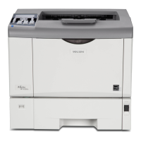
4. Interlock switch base [A] ( x 4, all s)
• Removing the spring [B] first makes this procedure easier.
• Remove all the connectors after the interlock switch base has been removed.
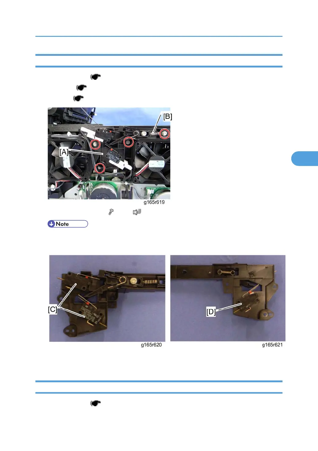
5. Two interlock switches [C] at the outside of the base and one interlock switch [D] at the inside of the
base (hooks)
Fusing Fan Motor
1. Operation panel ( p.24)
Electrical Components
67
 Loading...