PRINTER ENGINE SERVICE MODE
G065 5-6 SM
5.3.1 SERVICE PROGRAM MODE TABLES
Service Table Key
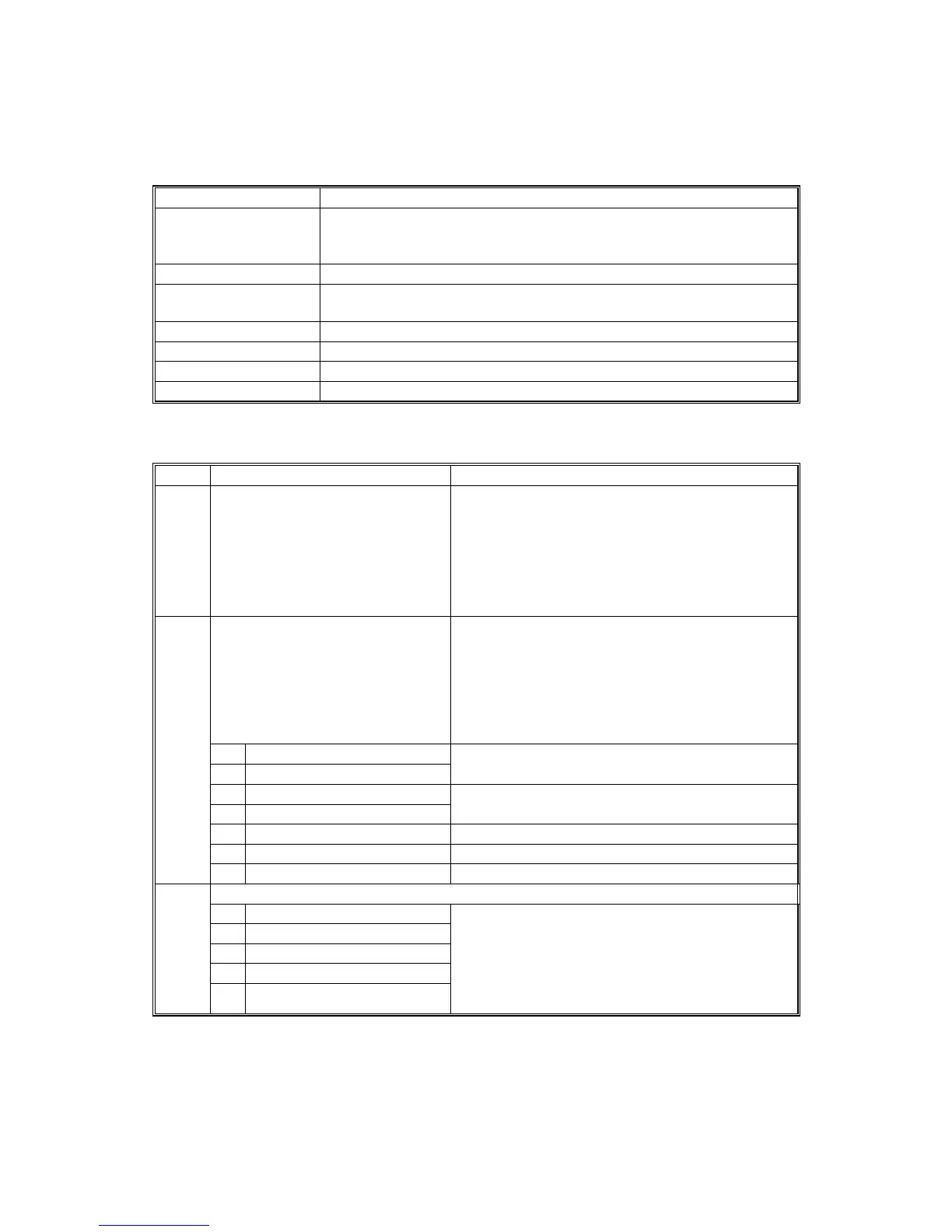
Notation What it means
[range / default / step] Example: [–9 ~ +9 / +3.0 / 0.1 mm step]. The setting can be
adjusted in the range ±9, value reset to +3.0 after an NVRAM reset,
and the value can be changed in 0.1 mm steps with each key press.
italics Comments added for reference.
* Value stored in NVRAM. After a RAM reset, this default value
(factory setting) is restored.
DFU Denotes “Design or Factory Use”. Do not change this value.
Japan only The feature or item is for Japan only. Do not change this value.
(S) Sideways feed direction (LEF)
(L) Lengthwise feed direction (SEF)
1. Feed (SP1000-00)
SP1 Mode Number Function and [Setting]
1001*
Sub-Scan Registration
Adjustment
Adjusts the printing leading edge registration
using the trimming area pattern (SP2902-03,
No.11).
[+9 ~ –9 / 3.0 / 0.1 mm]
Use #(Enter) to toggle between ± before
entering the value.
Specification: 3 ±2 mm
Side-to-Side Registration Adjusts the printing side-to-side (main scan)
registration. Changing this setting adjusts the
printing starting position. These settings should
be adjusted after the optical unit or laser
synchronization detection board is replaced.
Reduce the value to move the image closer to
the operation panel side of the machine.
01 Tray 1
02 Tray 2
[–9 ~ +9/ +3.0 mm / 0.1 mm step]
03 Tray 3
04 Tray 4
[–9 ~ +9/ +2.0 mm / 0.1 mm/step]
05 Duplex Tray [–9 ~ +9/ +0.0 mm / 0.1 mm/step]
06 By-pass Tray [–9 ~ +9/ +3.0 mm / 0.1 mm/step]
1002*
07 LCT [–9 ~ +9/ +1.5 mm / 0.1 mm/step]
Registration Buckle Adjustment
01 Paper Feed Trays, LCT
02 Duplex Tray
03 By-pass Tray
04 Tray 1
1003*
05 By-pass Thick
Adjusts the relay clutch timing at registration.
Relay clutch timing determines the amount of
paper buckle at registration. (A “+” setting
causes more buckling.)
[–9 ~ +9 / +0.0 mm (1 mm for 1st Tray Feed) /
0.1 mm step]
 Loading...


