IMAGE TRANSFER AND PAPER SEPARATION
SM 6-45 G065
Detailed
Descriptions
6.12.2 BELT DRIVE MECHANISM
After the main motor switches on
during printing, the transfer belt
contact clutch [A] switches on after
a specified interval and the cam [F]
makes a half-turn to raise the
contact lever [E] and bring the
transfer belt [D] into contact with the
drum.
The actuator [C], on the same axis
as the cam, and the transfer belt
position sensor [B] detect whether
the drum and transfer belt are in
contact.
When the main motor is off, or when
the ID sensor pattern is being
measured, the transfer belt unit
separates from the drum.
The ID sensor pattern must not be
transferred to the belt. Also, the transfer belt and drum must not remain in contact
for too long, to prevent contamination of the drum with oil or other foreign material
from the transfer belt.
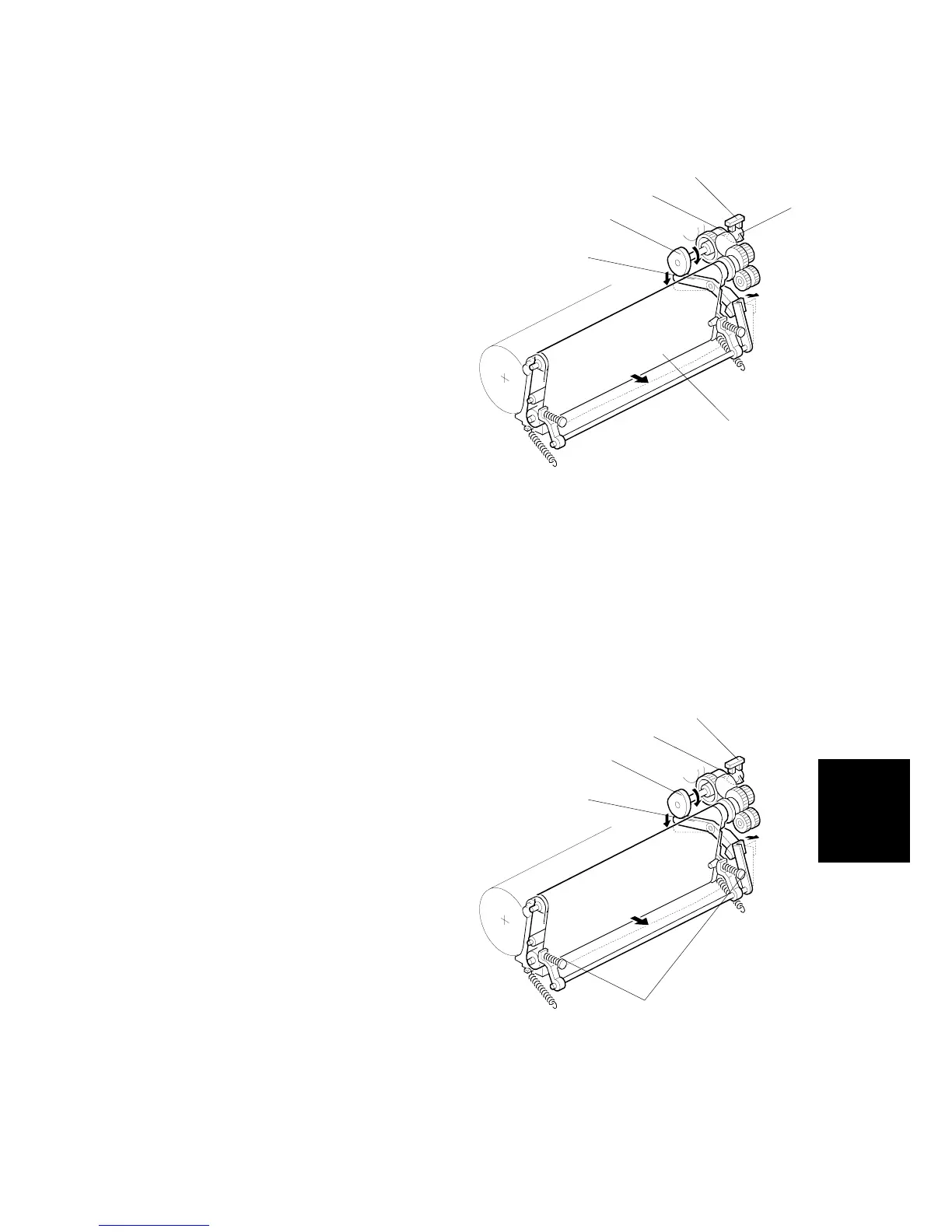
6.12.3 TRANSFER BELT UNIT CONTACT MECHANISM
The belt contact and release
mechanism consists of the belt
contact clutch [A], cam [B], and
contact lever [C]. The belt contact
clutch turns on and the cam
attached to the clutch rotates half a
complete rotation. The contact
lever, riding on the cam, is lifted up
and the springs [D] push the belt
into contact with the drum.
The transfer belt position sensor [E]
detects the home position of the
cam (this is when the belt is away
from the drum). The belt must be
released from the drum between
print jobs in order to prevent the ID
sensor pattern from being rubbed
off and to prevent contamination of
the drum from the surface of the
belt.
G065D563.WMF
G065D563.WMF
[C]
[B]
[A]
[F]
[E]
[D]
[D]
[E]
[A]
[B]
[C]
 Loading...


