PRINTER ENGINE SERVICE MODE
G065 5-10 SM
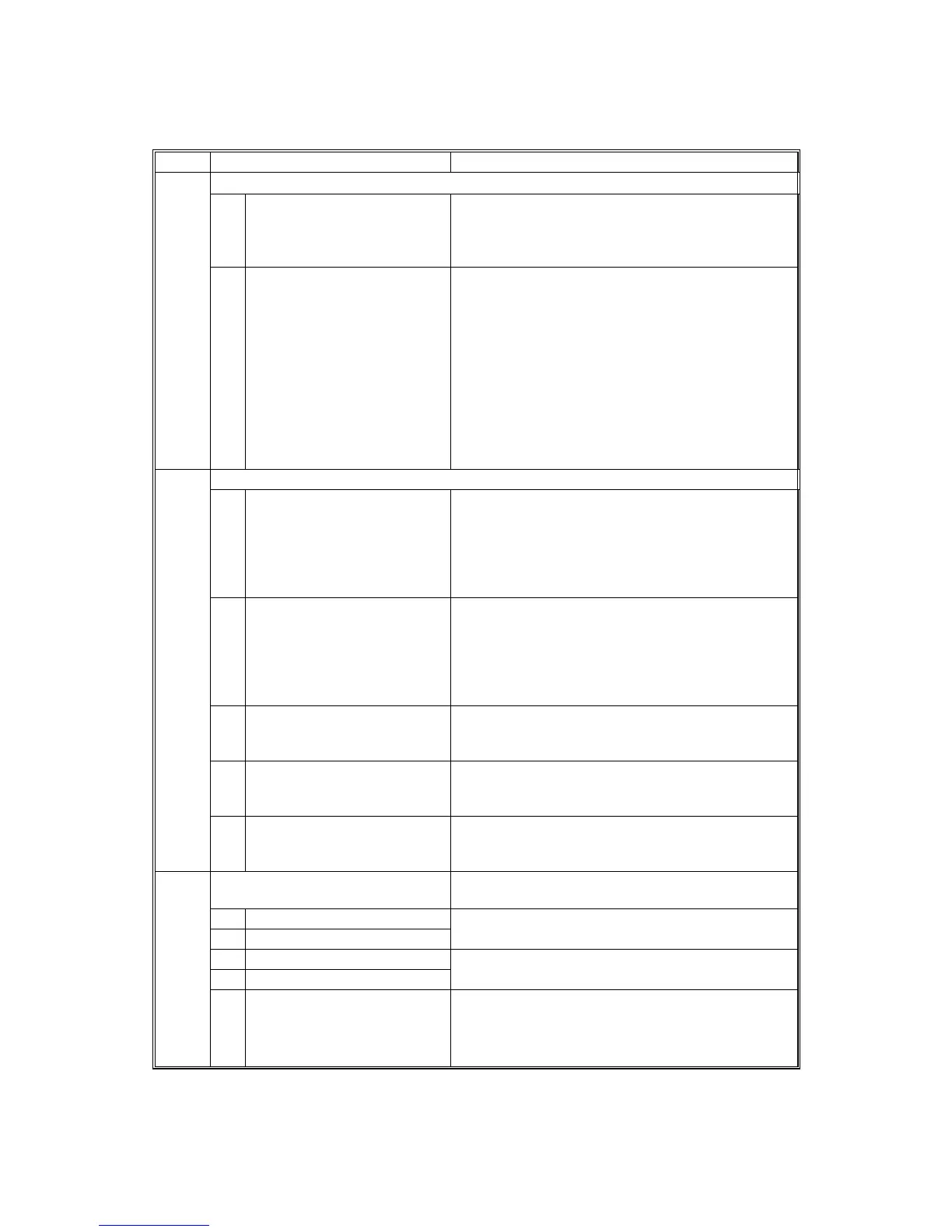
2. Drum (SP2000-00)
SP2 Mode Number Function and [Setting]
Charge Roller Bias Adjustment
01 Image Pattern
Adjusts the voltage applied to the charge roller
for the image area to maintain a charge of –800
V on the OPC drum surface.
[–1,000 ~ –2,000 / –1,480 V / 10 V step]
2001*
02 ID Sensor Pattern
Adjusts the voltage applied to the charge roller
when making the ID sensor pattern (for charge
roller voltage correction). The actual charge
roller voltage is this value plus the value of
SP2001-01.
[0 ~ 700 / 200 V / 10 V step]
The default is adjusted automatically based on
the number of prints.
00 K ~ 10 K: 200 V
10 K ~ 50 K: 230 V
50 K ~ 150 K: 340 V
Charge Roller Voltage
01 Correction 1
Adjusts the lower threshold value for the charge
roller correction. DFU
When the value of V
SP
/V
SG
is greater than this
value, the charge roller voltage increases by 30
V (e.g., from –1,480 to –1,510).
[0.1 ~ 1.0 / 0.85 / 0.05 step]
02 Correction 2 Adjusts the upper threshold value for the charge
roller correction. DFU
When the value of V
SP
/V
SG
is greater than this
value, the charge roller voltage decreases by 30
V (absolute value).
[0.1 ~ 1.0 / 0.9 / 0.05 step]
03 Adjustment 1 Adjusts the lower limit value for charge roller
voltage correction. DFU
[–1,000 ~ –2,000 / 1,480 V / 10 V step]
04 Adjustment 2
Adjusts the upper limit value for charge roller
voltage correction. DFU
[–1,000 ~ –2,000 / 2,000 V / 10 V step]
2005*
05 Step Adjusts the correction voltage adjustment step
size. DFU
[0 ~ 100 V / 30 V / 10 V step]
Printing Erase Margin Adjusts the leading edge (top), trailing edge
(bottom), left, and right margins.
01 Leading Edge
02 Trailing Edge
[0 ~ 9.0 / 3 / 0.1 mm step]
Specification: ±2 mm
03 Right Edge
04 Left Edge
[0 ~ 9.0 / 2 / 0.1 mm step]
Specification: ±1.5 mm
2101*
05 Trailing Edge – Back side Adjusts the trailing edge erase margin on the
reverse side of duplex prints.
[0 ~ 9.0 / 1.2 / 0.1 mm step]
Recommended: 2
±
1.5 mm
 Loading...


