BOARD STRUCTURE
G065 6-4 SM
6.2 BOARD STRUCTURE
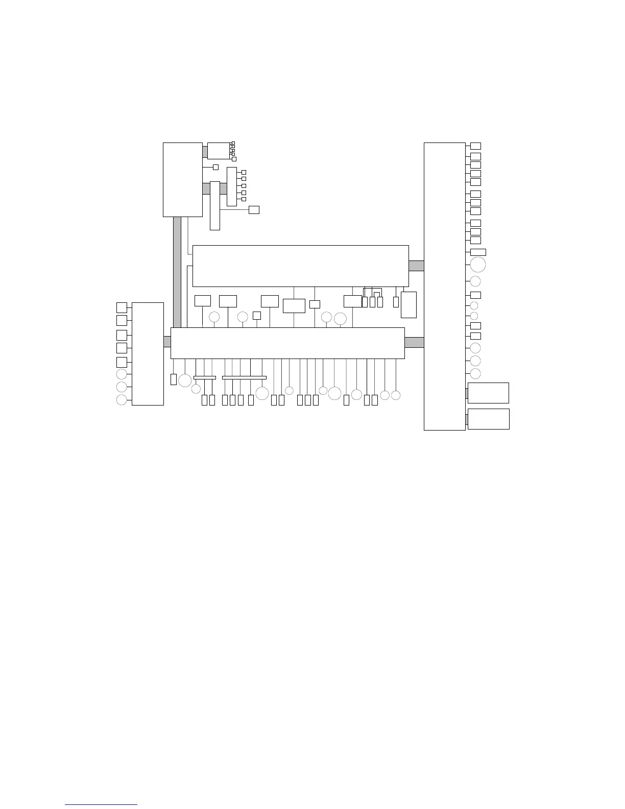
6.2.1 BLOCK DIAGRAM
This machine employs the GW (Grand Workware) architecture, which allows the
printer to be expanded by installing simple modular components (ROM DIMMs) on
the controller board.
Here is a brief summary of the boards and their functions. For more details, refer to
the Point-to-Point diagram and list of components supplied with the printer.
BICU (Base Engine and Image Control Unit)
Controls all machine functions both directly and through other control boards.
LDB (Laser Diode Board)
Powers the laser diode. Output level is controlled to compensate for changes in
temperature and humidity to maintain constant light intensity.
Controller (CB)
Controls memory and all peripheral devices. The Controller Board is equipped with
slots to accommodate the following interfaces: HDD, PCMCIA, NIB, IEEE1284,
IEEE1394.
BICU
Mother Board
Controller
DUPLEX
PFCB
M
M
M
xxx
Operation Panel
PSU
IOB
SOL
CL
M
M
CL
CL
CL
PTU
LCT
HVPS
CLCL
CL
Fan
Fan
M
Fan
CL
M
LDB
G065D998.WMF
 Loading...


