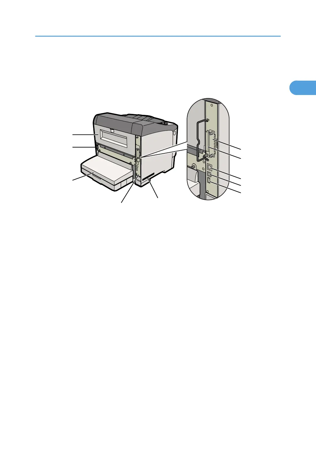
Exterior: Rear View
This section introduces the names of the various parts on the rear and left side of the printer and outlines
their functions.
1. Rear Cover
Remove this to install the optional duplex unit or to replace the fusing unit.
2. Power Connector
Connect the power cord to the printer here. Insert the other end of the cable into a nearby wall outlet. Do not
use extension leads or adaptor plugs to connect this printer to a wall outlet.
3. Paper Tray Cover
Keeps paper in the tray free of dust.
4. Controller Board
Slide this out to install the hard disk or SDRAM module.
5. Intake Vent
Prevents the printer's internal components overheating by letting in cool air through this vent.
Do not block or obstruct the ventilator areas. Doing so can result in malfunctions caused by build up of heat inside
the printer.
6. Optional Interface Board Slot
Install an optional interface board here. The Gigabit Ethernet board, Wireless LAN interface unit, or IEEE1284
interface board can be installed in this slot.
7. SD Card Slots
Remove the cover and install SD cards here. Install the data overwrite security unit or IPDS unit in the upper slot.
Install the VM card in the lower slot.
8. Ethernet Port
Use this port to connect the printer to a network via an Ethernet cable (RJ-45 connector).
Exterior: Rear View
15
 Loading...