INSTALLATION
23
2.7 Installation on appliances that are old or
that need to be updated
When the thermal units are installed on old systems or
those requiring modernisation, check that:
The ue is suitable for the temperature of the ue
gases, calculated and built according to the stand-
ard, as straight as possible, airtight, insulated, and
has no blockages or constrictions. Refer to paragraph
“2.13 Flue gas exhaust and combustion air suction” for
further information
The electrical system is installed by qualied person-
nel and complies with the specic standards
The fuel supply line (and tank, if installed) respect the
specic standards
The expansion vessel ensures the total absorption of
the expansion of the uid in the system
The ow rate, discharge head and ow direction of
the circulation pumps are correct
The system has been washed to remove sludge and
encrustations, and the seals have been checked
A treatment system is tted when the values of the
supply/make-up water are different from those
indicated in the “2.14 Filling the heating system and
eliminating air” paragraph.
a
The manufacturer is not liable for any damage re-
sulting from the incorrect construction of the ue
gas exhaust system.
Handling and removing the packaging
9
Do not remove the cardboard packaging until the
place of installation has been reached.
9
Before transporting and removing the package,
put on protective clothing (PPE) and make sure you
have the right equipment and tools for the size and
weight of the appliance.
9
This operation must be carried out by several peo-
ple, using equipment suitable for the size and
weight of the appliance. Make sure the load does
not become unbalanced during handling.
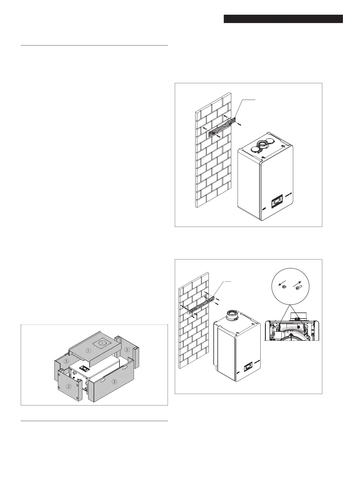
To remove the packaging, proceed as follows:
− Remove the box.
− Remove the front protective element (1).
− Remove the upper and lower protective elements
(2).
− Remove the side protective elements (3).
− Pull off the protective bag.
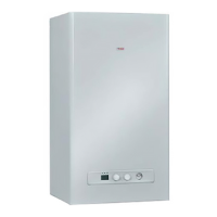
2.8 Assembling the boiler
9
The Condexa HPR thermal modules are supplied
with a bracket for wall-mounting.
9
Check that the wall on which the appliance is to
be installed is sufciently solid and guarantees the
safe anchorage of the screws.
For the assembly, proceed as follows:
position the boiler support plate (F) on the wall and
use a spirit level to make sure it is perfectly horizontal
mark the position of the holes (ø 6 mm) for securing
the boiler support plate (F)
make sure all the measurements are exact, then drill
the holes using drill tips with the diameters indicated
above
fasten the plate to the wall.
CONDEXA HPR 35-45
F
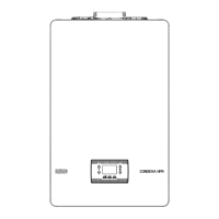
Condexa HPR 55 -70
To ensure the boiler is rmly fastened to the wall, replace
the screws on the back of the boiler with the longer ones
contained in the bag supplied with the appliance.
CONDEXA HPR 55-70
F
9
Before making the hydraulic connections, the pro-
tection plugs must be removed from the delivery,
return and condensate drain piping.
 Loading...