INSTALLATION
25
10 9 11
4
5
6
7
8
1
1
2
MI
RI
SE
13
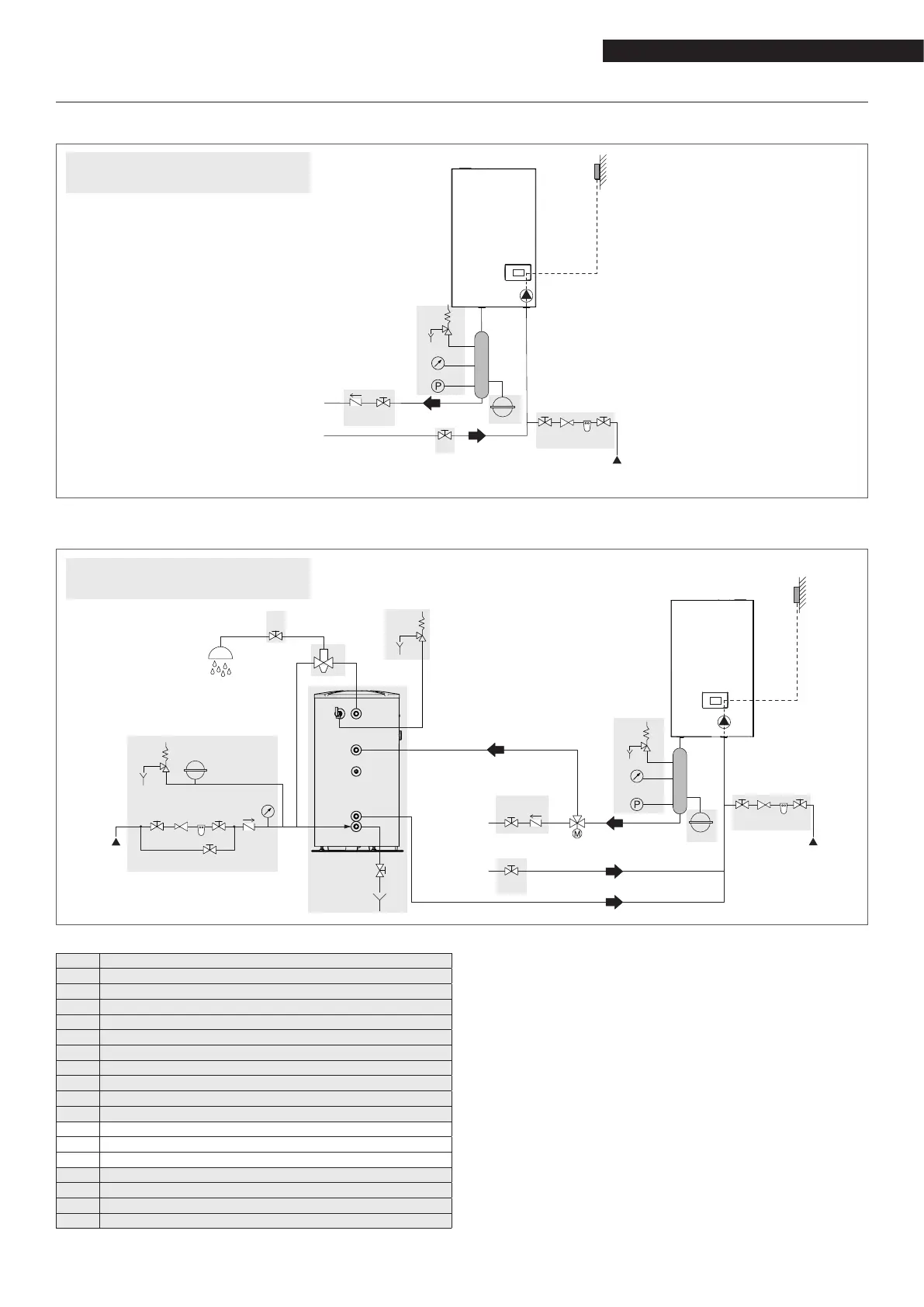
Layout 2: circuit with boiler directly connected to heating system and DHW tank (check that the pump discharge
head is sufcient to ensure adequate circulation)
12
21
1
4
1
1
5
6
1 10 9 1
1
2
6
5 4
3
11
5
6
7
8
10 9 11
7
SE
MI
RI
EAF
EAF
UAC
13
9
The DHW and heating circuits must be completed
with expansion vessels of adequate capacity and
correctly-sized safety valves. The discharge of the
safety valves and appliances must be connected to
a suitable collection and disposal system (see the
price list catalogue for compatible accessories).
9
The selection and installation of the system com-
ponents is the responsibility of the installer, who
must respect the standards of good practice and
current legislation.
9
Special supply/make-up water must be conditioned
using suitable treatment systems.
a
It is forbidden to operate the boiler and circulators
without water.
9
On Condexa HPR 35-45 models, the diverting valve
(12) can be installed in the boiler.
2.9 Schematic hydraulic systems
Layout 1: circuit with boiler directly connected to heating system (check that the pump discharge head is suf-
cient to ensure adequate circulation)
Components NOT managed
directly by the boiler
1 Disconnector valve
2 Non-return valve
3 Anti-burn mixer valve
4 Expansion vessel
5 Safety valve
6 Discharge
7 Pressure gauge
8 Minimum pressure switch
9 Softener filter
10 Pressure reducer
11 Storage tank
12 Diverting valve
13 Boiler circulator
SE Outdoor temperature sensor
MI High-temperature system delivery
RI High-temperature system return
EAF Cold water inlet
UAC DHW outlet
Components NOT managed
directly by the boiler
 Loading...