INSTALLATION
32
CONDEXA HPR 35-45
CONDEXA HPR 55-70
2.13
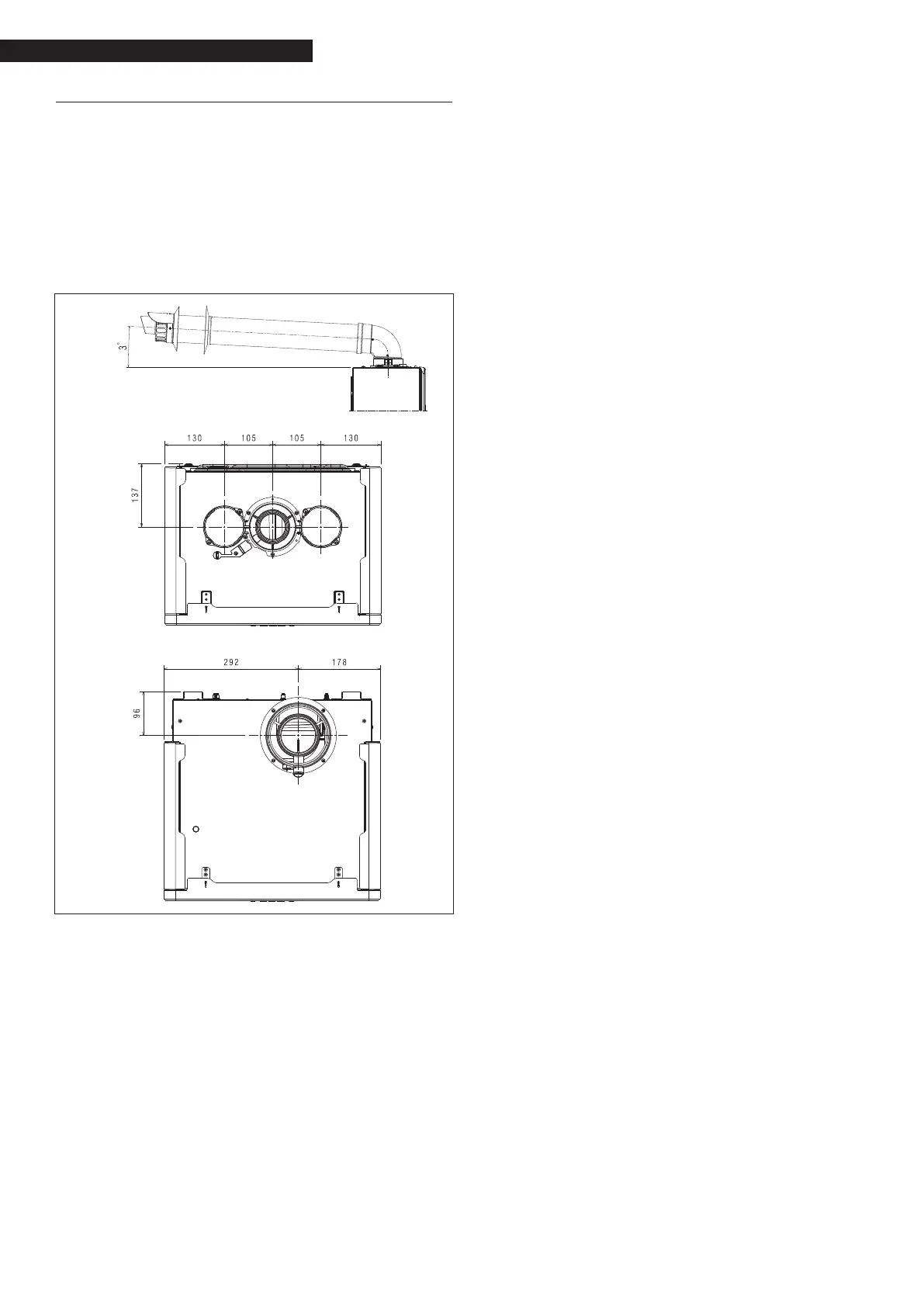
Flue gas exhaust and combustion air suction
To evacuate the combustion products, refer to UNI 7129-
7131. Always comply with the local regulations of the re
brigade and gas company, and with any possible mu-
nicipal regulations.
It is essential for ue gas evacuation and boiler combus-
tion air transfer that only original pipes are used (apart
from type C6, as long as it is certied), and that the con-
nection is made as explained in the instructions supplied
with the ue gas accessories.
A single ue can be con-
nected to several appliances provided that every appli-
ance is the condensing type.
9
9
Do not connect this appliance’s ue gas extrac-
tion pipes with those of other appliances, unless
this is specically authorised by the manufacturer.
Non-compliance with this precaution may cause a
build-up of carbon monoxide in the room where
the appliance is installed. This could jeopardise
people’s health and safety.
9
For more information on discharge pipes for ther-
mal modules connected in a cascade system, refer
to the price list catalogue and the instructions sup-
plied with the relative accessories.
9
Make sure the combustion (intake) air is not con-
taminated by:
− waxes/chlorinated detergents
− chemical products based on swimming pool
chlorine
− calcium chloride
− sodium chloride use to soften water
− refrigerant leaks
− paint or varnish removers
− hydrochloric acid/muriatic acid
− cements and glues
− anti-static softeners used in dryers
− chloride used for domestic or industrial applica-
tions as detergent, whitener or solvent
− adhesives used to x construction products etc.
9
To prevent contamination of the thermal module,
do not install suction line air intakes and ue gas
discharge pipes near:
− dry-cleaners/laundry rooms and factories
− swimming pools
− metal processing plants
− beauty parlours
− fridge repair shops
− photo-processing facilities
− body-shops
− plastics manufacturing plants
− furniture construction areas and plants.
9
The condensing appliances described in this man-
ual must be installed with ue gas pipes complying
with current legislation and purposely designed for
this specic use.
9
Check that pipes and joints are not damaged.
9
Joint seals must be made with materials that can
withstand the acidity of the condensate and the
temperatures of the ue gases.
9
Make sure the pipes are correctly assembled ac-
cording to the direction of the ue gases and the
descent of any possible condensate.
9
Inadequate or incorrectly sized ue gas pipes may
increase combustion noise, create condensate ex-
traction issues and negatively impact on the com-
bustion parameters.
9
Check that pipes are suitably far (min. 500 mm)
from ammable or heat-sensitive construction el-
ements.
9
Check that no condensate builds up along the pipe.
To this end, the pipe should have a gradient of at
least 3° degrees towards the appliance if there is a
horizontal section. If the horizontal section or the
vertical one is more than 4 metre long, a drain-trap
for the condensate must be provided at the bottom
of the line. The height of the drain-trap must be at
least equal to “H” (see gure A page 34). The drain-
trap discharge must therefore be connected to the
sewerage system.
a
It is forbidden to obstruct or choke the ue gas pipe,
or the combustion air suction pipe (if installed).
a
It is forbidden to use pipes not purposely designed
for this function, as the contact with the conden-
sate would quickly damage them.
Installing the ue gas pipes
− Position the discharge pipe so the connection is
fully up against the ue gas turret of the boiler.
 Loading...