MAINTENANCE AND CLEANING
49
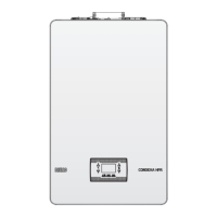
CONDEXA 55-70 HPR
D
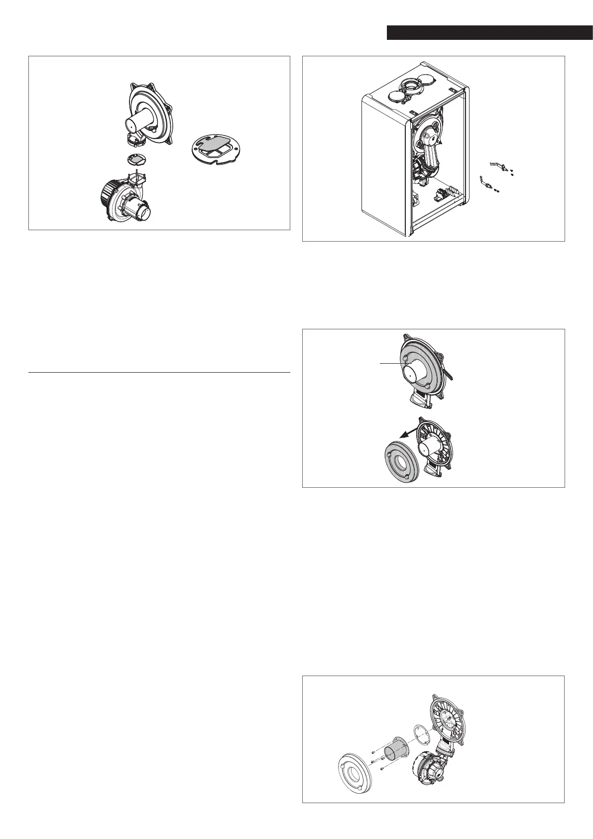
To access the check valve:
remove the fan by unscrewing the 4 screws (D) xing it
to the conveyor
make sure there are no foreign material deposits on the
membrane of the check valve and if any remove them
and checking for damage.
check the valve opens and closes correctly
re-assemble the components in reverse order, making
sure the check valve is put back in the correct direction.
If maintenance has been carried out on the check valve,
make sure it is correctly repositioned to ensure the system
operates properly and safely.
4.1 Disassembling the internal components
Disassembling the air-gas conveyor
Switch off the electricity supply by turning the main
system switch OFF.
Close the gas shut-off valve.
Remove the casing as explained in paragraph “2.10 Re-
moving the casing”.
Disconnect the connecting cables of the electrodes.
Disconnect the power cables of the fan.
Take out the clip (A) of the mixer.
Loosen the nut of the gas train (B).
Take out and rotate the gas train.
Rem
ove the 4 nuts (C) that hold the combustion unit.
Take out the air/gas conveyor assembly including the
fan and mixer, being careful not to damage the insulat-
ing panel and the electrodes.
Check that the burner insulating panel and the sealing
gasket are undamaged and replace them if necessary,
following the relative procedure.
Removing the ignition electrode, the detector electrode
Remove the components as described in the chapter
“REMOVING THE COMBUSTION UNIT”.
Loosen and remove the screws (W) holding the elec-
trodes.
The removal and eventual replacement of the electrodes
also involves the replacement of the sealing gaskets.
Once the operations are nished, carefully reassemble
all the components, following the above instructions in
reverse order.
Always ensure that the electrodes are positioned cor-
rectly and respect the reference position indicated in
the gure (maintenance of the ionisation electrode).
To close the screws xing the electrodes, use a tighten-
ing torque of 2 Nm.
Once the operations are nished, put back all the
components, following the above instructions in the
reverse order.
Turn the power and gas feeding to the boiler back on.
W
Replacing the burner insulating panel
Remove the burner insulating panel (A) by inserting a
blade just under the surface (as shown in the figure).
Remove any residual fixing adhesive.
Fit the new burner insulating panel.
The new insulating panel does not need to be fixed
with an adhesive as its geometric form ensures perfect
coupling with the heat exchanger flange.
A
Disassembling the burner
Switch off the electricity supply by turning the main
system switch OFF.
Close the gas shut-off valve.
Remove the casing as explained in paragraph “2.10 Re-
moving the casing”
.
Remove the insulating panel as explained above.
Remove the
4 screws (D) xing the burner to the convey-
or, then take it out along with the gasket (E).
Replace the burner.
Ret the burner, following the above steps in re
verse
order and remembering to insert the gasket.
To close the burner screws xing use a tightening torque
of 3.5 Nm. If the insulation panel is damaged, replace it
as described above.
After completing all the operations, reassemble all the
components, following the above steps in reverse or-
der.
Turn the power and gas feeding to the boiler back on.
D
E
 Loading...