Publication 2098-IN005C-EN-P — March 2008
Commissioning Your Ultra3000 Drive 89
Configuring Your Ultra3000
Drive with DeviceNet
The procedures in this section are listed in this table and apply to
Ultra3000-DN drives with indexing.
Ultra3000 Drive Configuration Procedures
These procedures assume you have completed wiring the DeviceNet
interface connector on your Ultra3000-DN drive.
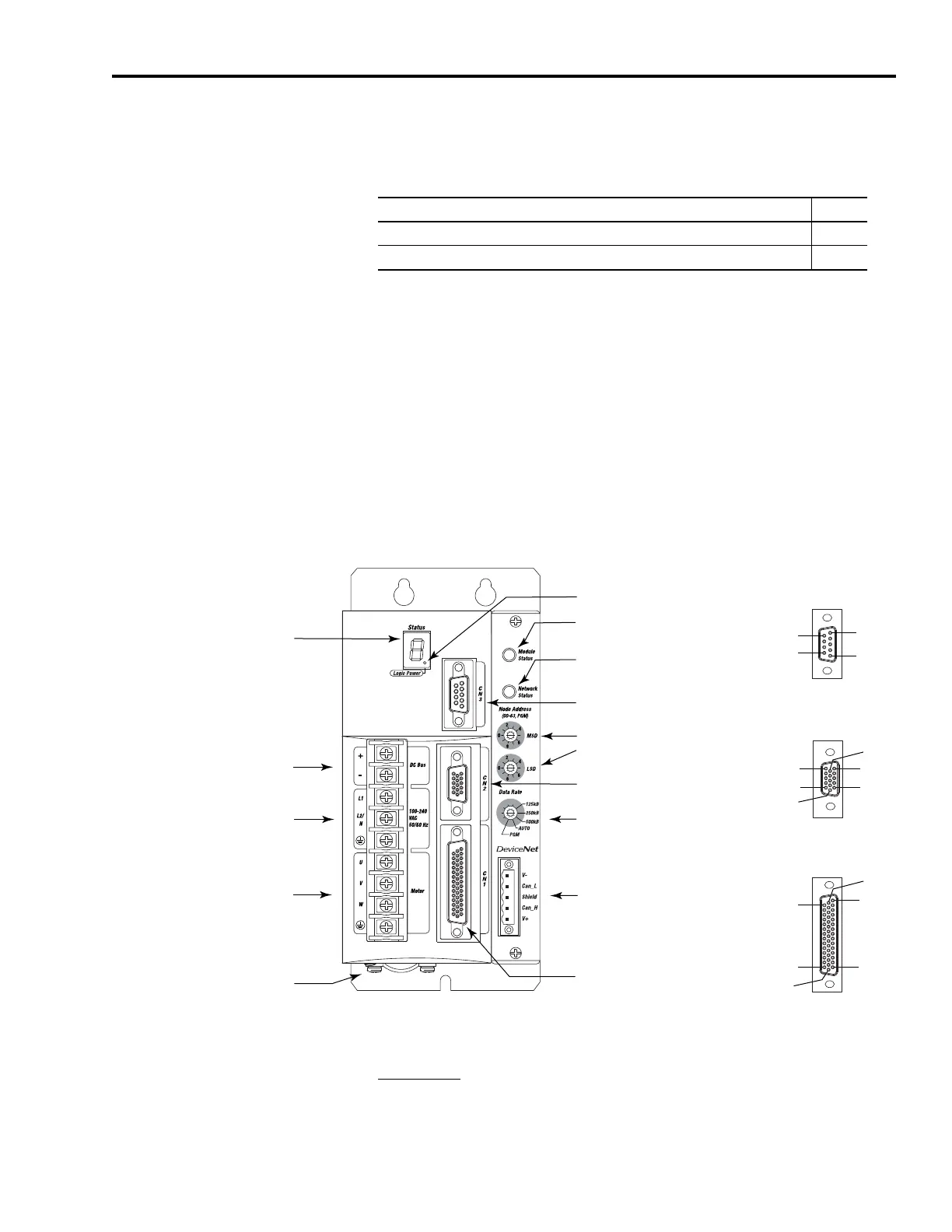
Front Panel Connections
Use this figure to locate the front panel connections on the
Ultra3000-DN 230V drives (500W, 1 kW, and 2 kW).
Front Panel Connections for 2098-DSD-005-DN, 2098-DSD-005X-DN,
2098-DSD-010-DN, 2098-DSD-010X-DN,
2098-DSD-020-DN, and 2098-DSD-020X-DN Drives
For CN1, CN2, and CN3 connector pin-out information, refer to the
Ultra3000 Digital Servo Drives Installation Manual, publication
2098-IN003
.
Procedure Page
Configure Your Ultra3000 Drive with DeviceNet 93
Apply Power to Your Ultra3000 Drive with DeviceNet 94
Pin 11
Pin 6
Pin 15
Pin 1
Pin 10
Pin 5
Pin 30
Pin 44
Pin 1
Pin 15
Pin 16
Pin 31
Pin 6
Pin 9
Pin 1
Pin 5
AC Input Power
Connections
Motor Power
Connections
DC Bus Connections for
Active Shunt Resistor Kit
Seven-segment
Status Indicator
Logic Power Indicator
CN3 9-pin
Serial Port
Connector
CN2 15-pin
Motor Feedback
Connector
CN1 44-pin
User I/O
Connector
DeviceNet Interface
Connector
Node Address
Switches
Data Rate Switch
Module Status Indicator
Network Status Indicator
Motor Power
Cable Shield Clamp
9-pin CN3
Serial Connector
15-pin CN2
Feedback Connector
44-pin CN1
I/O Connector

 Loading...


