EasyManuals Logo
Home>Rockwell Automation>Touch terminals>PanelView Plus 1000

Rockwell Automation PanelView Plus 1000 User Manual

Rockwell Automation PanelView Plus 1000
248 pages
To Next Page IconTo Next Page
To Previous Page IconTo Previous Page
Page #159 background imageLoading...
Page #159 background image
Publication 2711P-UM001I-EN-P - December 2008 159
Install and Replace Components Chapter 6
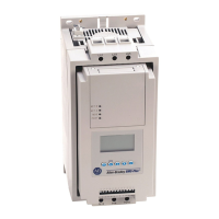
4. Remove the four screws that secure the LCD display for all other
displays.
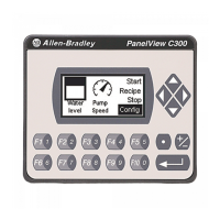
5. Lift the LCD display and detach the display connector from the
circuit board.
The circuit board layout may vary for each terminal model.
The location of the connector varies by model.
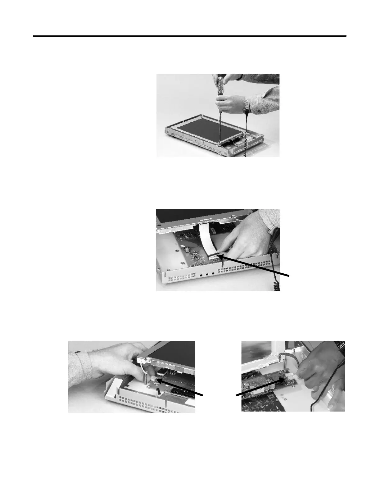
6. Detach the backlight connectors from the circuit board.
The 1250 has one or two backlight connectors depending on the
series of the display. The 1500 has four backlight connectors.
Display
Connector
Backlight
Connector
1250 1500

Table of Contents

Other manuals for Rockwell Automation PanelView Plus 1000

Questions and Answers:

Question and Answer IconNeed help?

Do you have a question about the Rockwell Automation PanelView Plus 1000 and is the answer not in the manual?

Rockwell Automation PanelView Plus 1000 Specifications

General IconGeneral
BrandRockwell Automation
ModelPanelView Plus 1000
CategoryTouch terminals
LanguageEnglish

Related product manuals