Publication 2711P-UM001I-EN-P - December 2008 161
Install and Replace Components Chapter 6
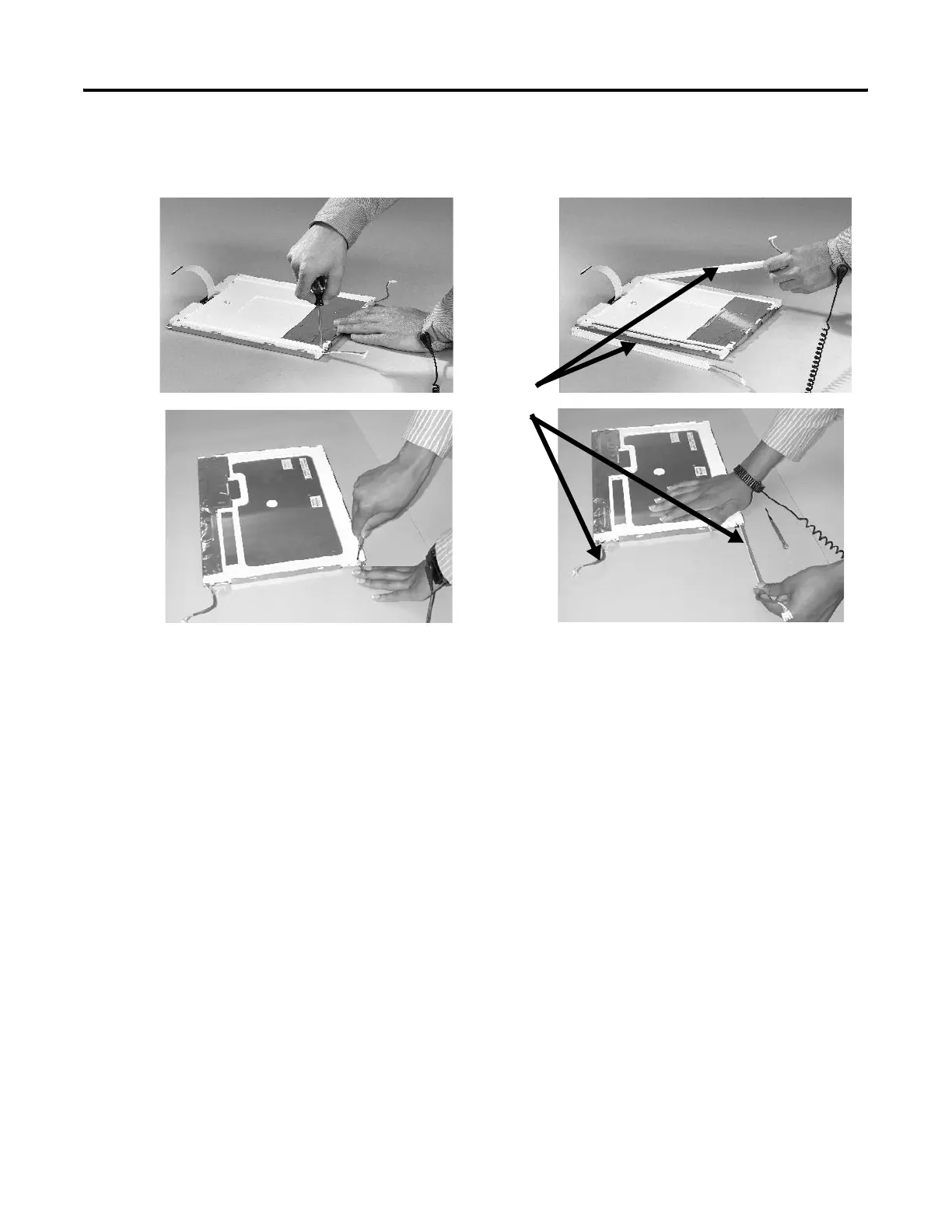
– For the 1500 series B displays, remove the tape and then
remove the backlights.
b. Insert the new backlights and then secure each with the same
screws from the previous step and torque to
0.117 Nm (1.04 lb•in).
9. Attach the LCD display connector to the circuit board.
Refer to step 5.
10. Attach the backlight connector to the circuit board.
Refer to step 6.
11. Secure the LCD display.
a. Attach the display bracket then secure the display in the
bracket for the 700 series C display.
b. Attach the four screws for all othe displays.
Tighten the screws and torque to 0.58 Nm (5…7 lb•in).
12. Replace the display module bezel.
Backlights
1250
1500

 Loading...