PowerFlex Digital DC Drive User Manual - Publication 20P-UM001C-EN-P - July 2008
3-50 Programming and Parameters
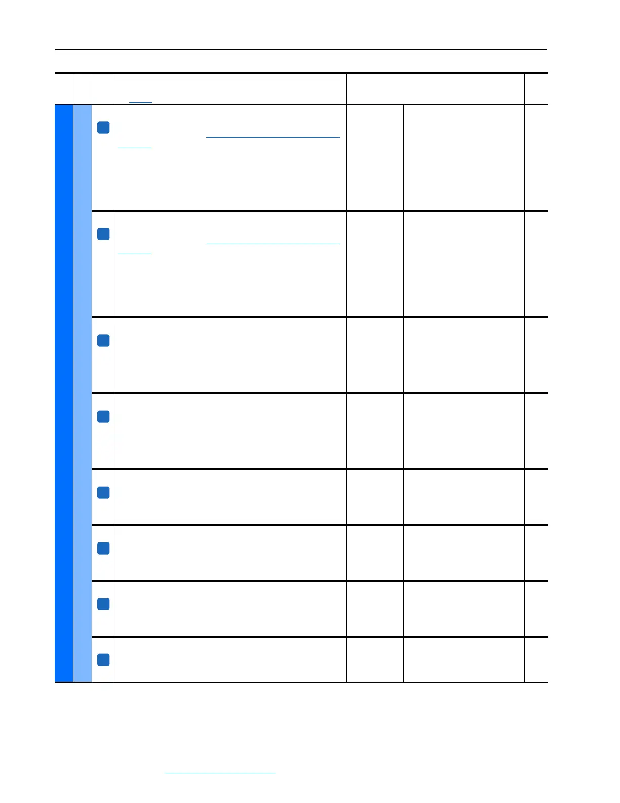
UTILITY
Diagnostics
401 [Spd Select 1]
Indicates the state of the assigned digital input, [Digital Inx Sel], set to
18 “Speed Sel 2”. Refer to Option Definitions for [Digital Inx Sel] on
page 3-66 for instructions on how to set digital input speed selects to
different speed references.
• “0” = Digital input [Digital Inx Sel] set to 18 “Speed Sel 2” not
asserted
• “1” = Digital input [Digital Inx Sel] set to 18 “Speed Sel 2” asserted
Note: By default, the state of this parameter is determined by digital
input 6.
Default:
Min/Max:
Read Only
0 / 1
400,
402
402 [Spd Select 2]
Indicates the state of the assigned digital input, [Digital Inx Sel], set to
19 “Speed Sel 3”. Refer to Option Definitions for [Digital Inx Sel] on
page 3-66 for instructions on how to set digital input speed selects to
different speed references.
• “0” = Digital input [Digital Inx Sel] set to 19 “Speed Sel 3” not
asserted
• “1” = Digital input [Digital Inx Sel] set to 19 “Speed Sel 3” asserted
Note: By default, the state of this parameter is determined by digital
input 7.
Default:
Min/Max:
Read Only
0 / 1
400,
401
403 [Ramp Select 0]
Indicates the state of the assigned digital input, [Digital Inx Sel], set to
25 “Acc2 & Dec2” or 26 “Accel 2”.
• “0” = Accel 1 ramp rate is selected
• “1” = Accel 2 ramp rate is selected
Note: This parameter can be assigned to indicate the state of a digital
input.
Default:
Min/Max:
Read Only
0 / 1
404
404 [Ramp Select 1]
Indicates the state of the assigned digital input, [Digital Inx Sel], set to
25 “Acc2 & Dec2” or 27 “Decel 2”.
• “0” = Decel 1 ramp rate is selected
• “1” = Decel 2 ramp rate is selected
Note: This parameter can be assigned to indicate the state of a digital
input.
Default:
Min/Max:
Read Only
0 / 1
403
651 [Encoder State]
Indicates the connection status of the digital encoder or tachometer.
• “0” = Fault
• ‘1” = OK
This parameter can be assigned to a digital output.
Default:
Min/Max:
Read Only
0 / 1
1188 [Accel Status]
Indicates the drive acceleration status.
• “0” = Off - Drive not accelerating
• “1” = “On” - Drive accelerating
Note: This parameter can be assigned to a digital output.
Default:
Min/Max:
Read Only
0 / 1
1189 [Decel Status]
Indicates the drive deceleration status.
• “0” = “Off” - Drive not decelerating
• “1” = “On” - Drive decelerating
Note: This parameter can be assigned to a digital output.
Default:
Min/Max:
Read Only
0 / 1
1190 [Fast Stop Status]
Indicates the drive fast stop status.
• “0” = “Off” - Drive is not fast stopping
• “1” = “On” - Drive is fast stopping
Default:
Min/Max:
Read Only
0 / 1
File
Group
No.
Parameter Name & Description
See page 3-2 for symbol descriptions
Values
Related
A
A
A
A
A
A
A
A
 Loading...


