PowerFlex Digital DC Drive User Manual - Publication 20P-UM001C-EN-P - July 2008
3-54 Programming and Parameters
UTILITY
Alarms
473 [FldLoss Flt Cfg]
Determines the response of the drive to a field loss condition (F6 “Fld
Current Loss”). If Par 497 [Field Reg Enable] is set to 0 “Disabled”,
this parameter should be set to 0 “Ignore”.
Note: Refer to Chapter 4 for a list of alarm and fault descriptions.
Default:
Options:
2 =
0 =
1 =
2 =
“Fault”
“Ignore”
“Alarm”
“Fault”
497
478 [Spd Loss Flt Cfg]
Determines the response of the drive to a speed feedback loss
condition (F91 Encoder Loss).
Note: Refer to Chapter 4 for a list of fault descriptions.
Default:
Options:
2 =
1 =
2 =
“Fault”
“Alarm”
“Fault”
481 [UnderVolt Thresh]
The AC input voltage level below which an undervoltage fault (F4 “AC
Undervoltage”) will be detected.
Note: Refer to Chapter 4 for a list of fault descriptions.
Default:
Min/Max:
Units:
230
0 / 1000
Vac
584 [OverCurrent Thr]
Value at which an overcurrent condition (F13 “Overcurrent”) will be
detected.
Note: Refer to Chapter 4 for a list of fault descriptions.
Default:
Min/Max:
Units:
175
0 / 250
%
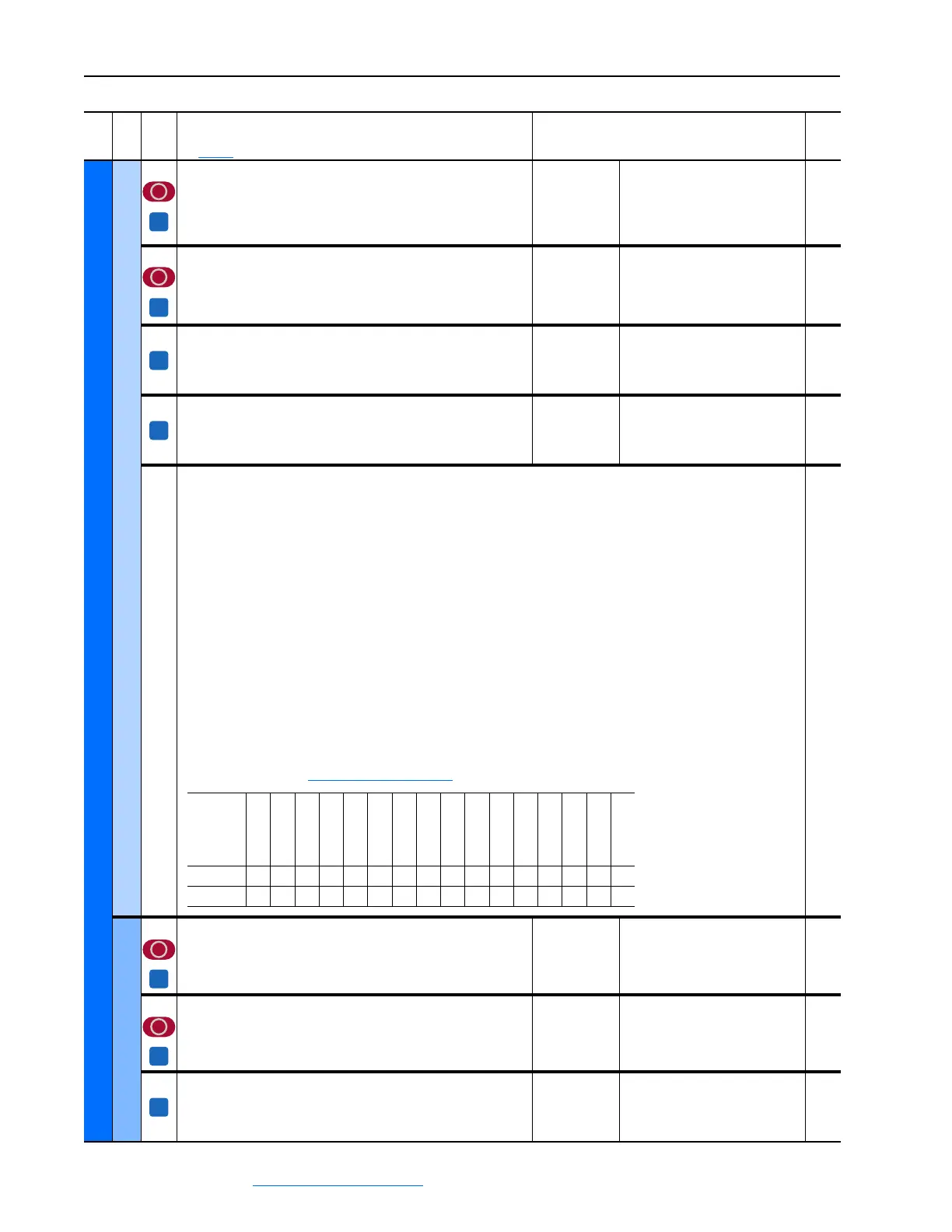
1380 [Drive Alarm 1]
Alarm conditions that currently exist in the drive. For each bit, 1=Condition true and 0=Condition false.
Bit 0 “DigInCflctA” - Digital input functions are in conflict.
Bit 1 “DigInCflctB” - A digital Start input has been configured without a Stop input or other functions are in conflict.
Bit 2 “DigInCflctC” - More than one physical input has been configured to the same input function.
Bit 3 “BipolarCflct” - Parameter 1322 [Direction Mode] is set to “Bipolar” or “Reverse Dis” and one or more of the following
digital input functions is configured: “Fwd/Reverse,” “Run Forward,” “Run Reverse,” “Jog Forward” or “Jog Reverse.”
Bit 4 “AnalogCflct” - Analog input functions are in conflict.
Bit 5 “CntactrCflct” - Contactor input functions are in conflict.
Bit 6 “Encoder Cflc” - Indicates an encoder configuration conflict.
Bit 7 “Overvoltage” - There is an overvoltage on the armature circuit.
Bit 8 “Over Temp” - The motor has exceeded its temperature rating (as signaled by the thermistor connected to the drive
terminals 78 and 79).
Bit 9 “Aux Input” - An auxiliary input interlock is open or a voltage (15 - 30 V) or reference signal is missing for the digital
input set to 14 “Aux Fault”.
Bit 10 “Field Loss” - The field current is too low.
Bit 11 “Encoder Loss” - The drive is not receiving a speed feedback signal.
Bit 12 “PwrUp Start” - Indicates that the drive is starting or has automatically resumed running at commanded speed after
drive input power is restored.
Note: Refer to Chapter 4 Troubleshooting on page 4-1
for information.
1322
User Defined
50 [UsrDsplyMult0]
Numerator in the calculation for user-defined, drive speed display
units.
Note: This parameter is not used.
Default:
Min/Max:
1
1 / 1073741823
51 [UsrDsplyDiv0]
Denominator in the calculation for user-defined, drive speed display
units.
Note: This parameter is not used.
Default:
Min/Max:
1
1 / 1073741823
53 [UsrValMult1]
Numerator in the calculation for scaling the user-defined, drive speed
display units.
Note: This parameter is not used.
Default:
Min/Max:
1
1 / 32767
File
Group
No.
Parameter Name & Description
See page 3-2 for symbol descriptions
Values
Related
A
A
A
A
Reserved
Reserved
Reserved
PwrUp Start
Encoder Loss
Field Loss
Aux Input
Over Temp
Overvoltage
Encoder Cflc
CntactrCflct
AnalogCflct
BipolarCflct
DigInCflctC
DigInCflctB
DigInCflctA
Default
xxxxx00000000000
Bit
1514131211109876543210
A
A
A
 Loading...


