PowerFlex Digital DC Drive User Manual - Publication 20P-UM001C-EN-P - July 2008
4-8 Troubleshooting
CntactrCflct
➁
Contactor input functions are in conflict:
• When Par 1391
[ContactorControl] is set to “None”, both relay outputs
(Pars 1392
[Relay Out 1 Sel] and 629 [Relay Out 2 Sel] and all digital inputs
([Digital Inx Sel]) cannot be set to “Contactor” or “ContactorDB”.
• With [ContactorControl] set to “Contactor”, one relay output and one digital
input must be set to “Contactor”. No output can be defined as
“ContactorDB”.
• With [ContactorControl] set to “Contactor+DB”, both relay outputs and one
digital input must be set to “Contactor”, “ContactorDB” and “Contactor”,
respectively.
Because any relay output can be configured as contactor or DB control and
any digital input as contactor status, care must be taken to correctly wire the
terminal blocks to match the parameter selections.
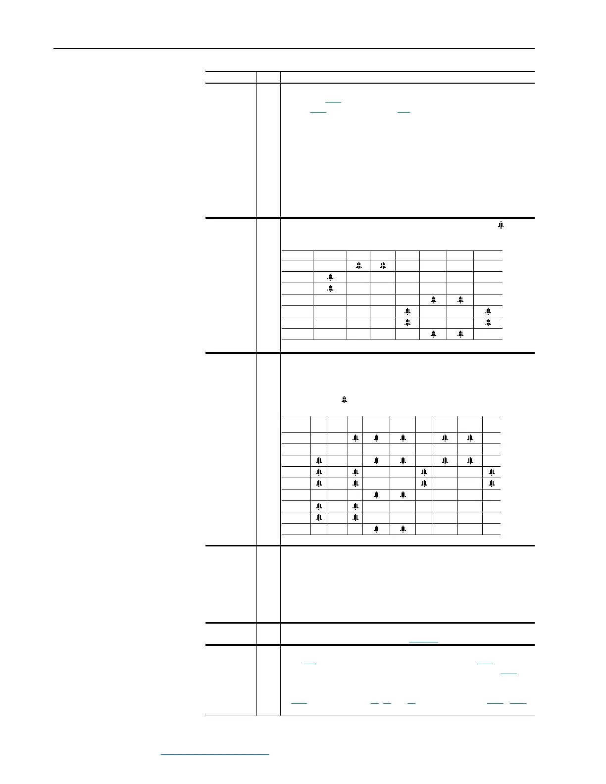
DigInCflctA
➁
Digital input functions are in conflict. Combinations marked with a “ ” will
cause an alarm.
DigInCflctB
➁
One of the following digital input conflicts exists:
• A digital Start input has been configured without a Stop input
• None of the digital inputs are configured for “Enable”
• Other digital input functions are in conflict. Combinations that conflict are
marked with a “ ” and will cause an alarm.
DigInCflctC
➁
More than one physical input has been configured to the same input function.
Multiple configurations are not allowed for the following input functions.
Forward/Reverse Run Reverse Run Forward
Jog Forward Jog Reverse Speed Select 1
Speed Select 2 Speed Select 3 Acc2 / Dec2
Accel 2 Decel 2 Run
Encoder Loss
➀
The drive is not receiving a speed feedback signal from the encoder. Refer to
the “Encoder Loss” fault description on page 4-4
for more information.
EncoderCflct
➁
One of the following has occurred:
• Par 414
[Fdbk Device Type] is set to 1 “Encoder” and Par 1021 [Encoder
Out Sel] is not set to 0 “Off”. If you are using an encoder, set Par 1021
[Encoder Out Sel] to 0 “Off”.
• More than one of the following parameters contains the same value: Pars
1021
[Encoder Out Sel], 70, 75 and 80 [Anlg Inx Sel], and/or 1323 - 1327
[DPI Px Select].
Alarm Type Description
Acc2/Dec2 Accel 2 Decel 2 Jog 1/2 Jog Fwd Jog Rev Fwd/Rev
Acc2/Dec2
Accel 2
Decel 2
Jog 1/2
Jog Fwd
Jog Rev
Fwd/Rev
Start
Stop-
CF Run Run Fwd Run Rev
Jog
1/2 Jog Fwd Jog Rev
Fwd/
Rev
Start
Stop-CF
Run
Run Fwd
Run Rev
Jog 1/2
Jog Fwd
Jog Rev
Fwd/Rev
 Loading...


