-82-
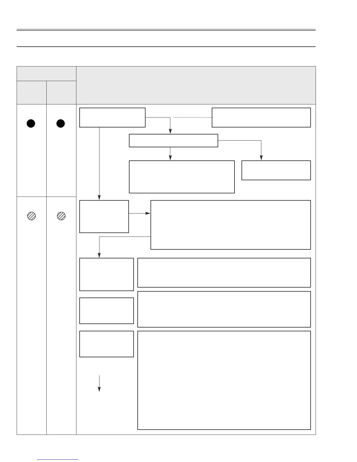
● No Power
This projector provides a function which can be specified a defective area simply by indicating the LEDs on the con-
trol panel. Connect the AC cord and turn the projector on and then check the LED indication.
■ Troubleshooting
POWER (red)
and WARNING
(red) indicators
are lighting?
Yes
Check power supply lines, S5V,S-5V, S16V, etc. on the Main
board.
- Refer to the diagram "Power Supply Lines".
An abnormality
occurs on the sec-
ondary power sup-
ply lines
Power failure detection diodes detect the fan operation stop.
Check FN901/902/903/904/905 and peripheral circuit.
Check connectors K8E/K8F from TH901/TH902.
- Refer to the diagram "Fan control circuit".
An abnormality
occurs on the fan
control circuits.
Check power starter signals as follows:
- PWR_SW signal (Power-on:H) is output from pin 12 of IC4801 and
sent to the Power Board and S16V, S16V_F, S6.5V, S5V, S-5V lines
are supplied.
- MAINON_SW signal (Power-on:H) is output from pin 80 of IC301
and sent to the Power Board and lamp ballast 375V line is supplied.
- 5V_SW signal (Power-on:H) is output from pin 336 of IC301 and
sent to IC1581, IC8251, IC8281, Q4601, Q4603, then 12V, 3.3V_D,
3.3V_A, -5V, 6.5V lines are supplied.
- 3.3V_SW signal (Power-on:H) is output from pin 76 of IC301 and
sent to IC3601, then 3.3V, 1.2V lines are supplied.
- 15V_SW signal (Power-on:H) is output from pin 79 of IC301 and
sent to Q591, then 15.5V line is supplied.
- FAN_SW signal (Power-on:H) is output from pin 81 of IC301 and
applied to the Fan power supply circuit.
An abnormality
occurs on power
starter signals.
Check following
items
The symptom indicates that the projector detected an
abnormality in the cooling fan operation or in the power
supply secondary circuits. Check fan operation and power
supply lines, and the driving signal status.
- POWER_FAIL (Error:L) signals are sent to IC301 via IC871
and IC1801, then IC301 shuts down the power supply circuit.
Does a indicator flash
or light?
The primary power supply circuit
does not operate properly.
Check Varistor (VA611).
Check Power Board.
Is fuse (F601) broken?
Check SS5V power supply line.
- When the main power switch is ON,
SS5V line is supplied to IC4801(Sub
CPU).
To next page
POWER
red/green
Indicators
WARNING
red
No
Yes
Yes
No
Troubleshooting
 Loading...