Compartment identification
9.4 Mounting, wiring, interfaces, compartment identification
SIMOCODE pro
System Manual, 05/2019, A5E40507475002A/RS-AD/004
167
9.4 Mounting, wiring, interfaces, compartment identification
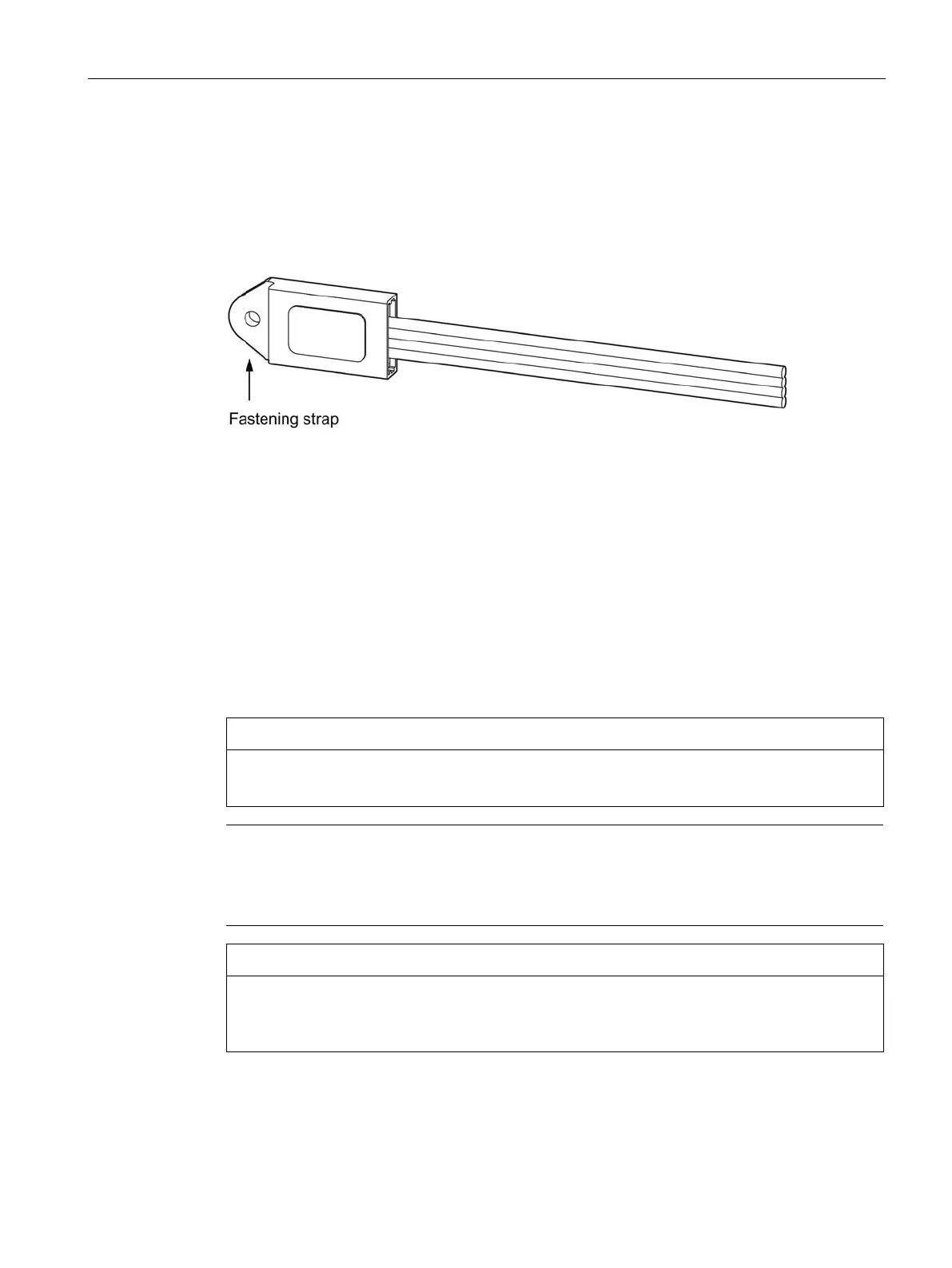
Mounting the initialization module in the switchboard
Mounting the initialization module with the mounting lugs in the switchboard
Figure 9-2 Mounting the initialization module
Wiring the initialization module
Unlike the other expansion components of the system, the initialization module does not
have a connector. It is intended for installation in the fixed part of the switchboard. Connect
the initialization module to a motor control center's control connector toward the switchboard
using the four connecting wires.
On the mating side, there is a withdrawable module to whose control connectors the
corresponding four connecting wires of the Y connecting cable are connected (see figure).
Connect each of the wires that are of the same color on the initialization module and the Y
connecting cable.
Incorrect wiring can destroy the initialization module.
Note
Cable routing
When wiring the initialization module make sure the individual conductors are routed as
close together as possible (ribbon cable).
Maximum length of the connecting cable
The total length of all cables must not exceed 3 m on either of the system interfaces of the
basic unit!
 Loading...