Description of system components
8.2 Operator panel (OP)
SIMOCODE pro
System Manual, 05/2019, A5E40507475002A/RS-AD/004
85
8.2 Operator panel (OP)
Function of the operator panel
The operator panel controls the motor feeder from the switchgear cabinet. It has an external
system interface on the front to allow easier parameterization or diagnostics via a
PC / programming device. This system interface (with cover for IP54) can be used to
connect (by means of the PC cable) a PC with the SIMOCODE ES (TIA Portal) software
installed or the memory module or the addressing plug.
On the rear system interface, it is connected to the basic unit or to an expansion module via
a connecting cable. It is supplied with power via the basic unit.
The operator panel is frequently installed in the front panels of motor control centers. It is
used in all device series. It also contains all the status LEDs available on the basic unit and
the "TEST/RESET" button, and facilitates access to the system interface from outside the
control cabinet.
The following are available:
● 5 buttons, of which 4 are freely parameterizable
● 10 LEDs, of which 7 are freely parameterizable
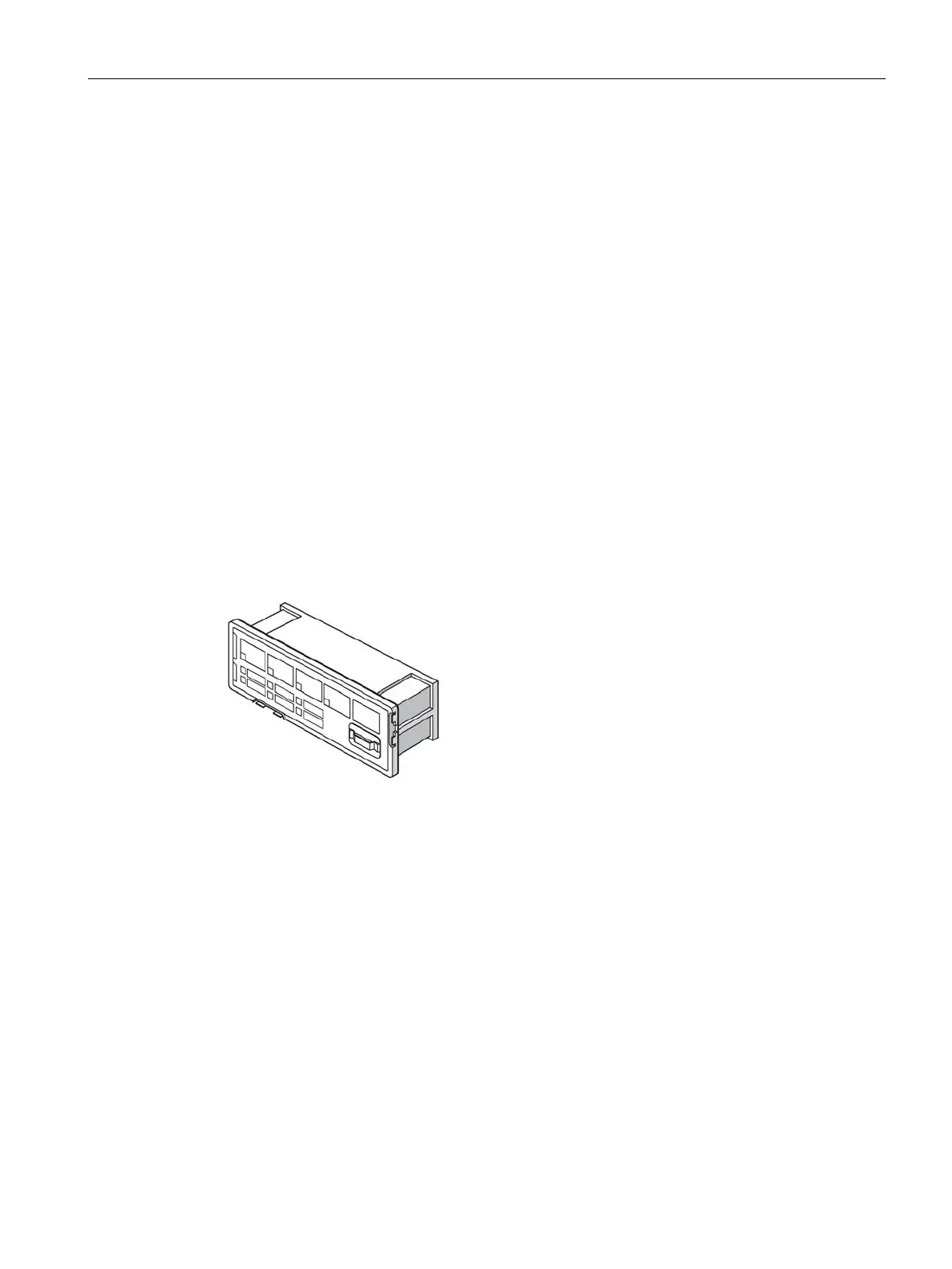
The following figure shows an operator panel:
Figure 8-2 Operator panel
 Loading...