Mounting, wiring, connecting, system interfaces, configuration guidelines
12.1 Mounting
SIMOCODE pro
System Manual, 05/2019, A5E40507475002A/RS-AD/004
191
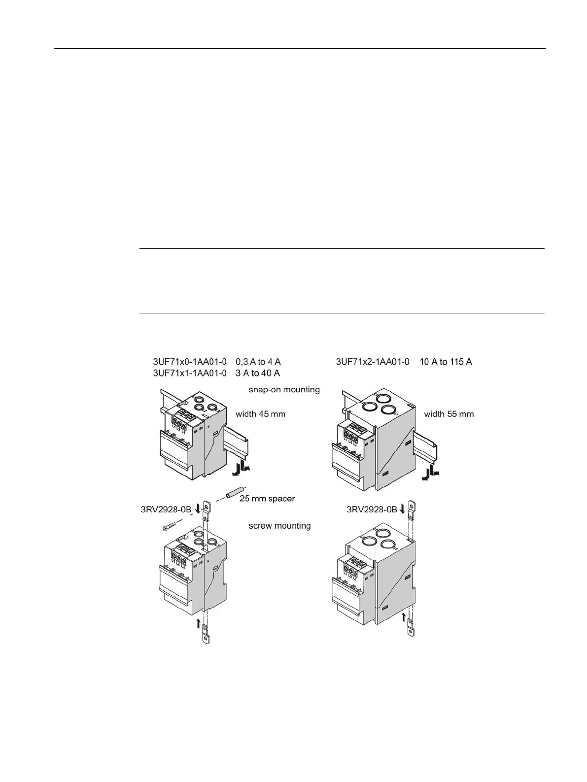
12.1.5 Mounting the current / voltage measuring modules
You can attach these system components as follows:
● Current / voltage measuring modules up to 115 A: Standard mounting rail mounting or
screw attachment with mounting lugs (article number: 3RV2928-0B) and screws for
mounting on a level surface. These mounting lugs are suitable only for current / voltage
measuring modules (and current measuring modules)! For current / voltage measuring
modules up to 25 A you will require an additional spacer, 25 mm in length.
● Current / voltage measuring modules up to 200 A: Standard mounting rail or screw
attachment.
● Current / voltage measuring modules up to 630 A: Screw mounting
/ voltage measuring modules with a current setting of up to 115 A can be connected
to the basic unit mechanically and installed as a unit (behind one another).
/ voltage measuring modules can only be mounted separately.
Figure 12-5 Mounting the current / voltage measuring modules UM+ with through-hole technology
 Loading...