Mounting, wiring, connecting, system interfaces, configuration guidelines
12.2 Wiring, connecting
SIMOCODE pro
222 System Manual, 05/2019, A5E40507475002A/RS-AD/004
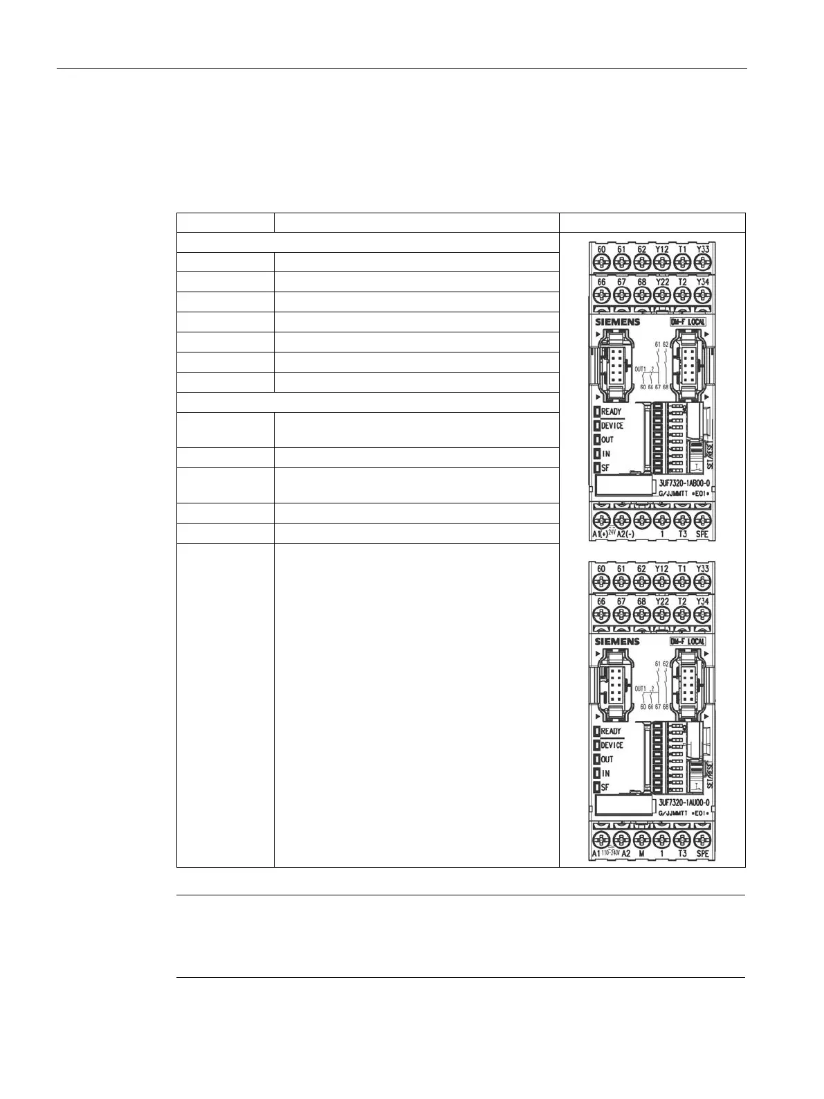
Terminal assignment for digital module DM-F Local
The following table shows the pin assignment of the removable terminals:
Table 12- 18 Terminal assignment of the removable terminals of the digital module DM-F Local,
24 V DC version and 110 to 240 V UC version.
Upper terminals
Digital module, relay outputs 1 (60) and 2 (66)
Relay enabling circuit 1, NO
Relay enabling circuit 2, NO
Sensor input channel 1, channel 2
Supply for sensor inputs (24 V DC, pulsed)
Y33 Start button (start after rising and falling edge)
A1 (+) Power supply connection 110 to 240 V AC/DC or
M Ground (reference potential for sensor inputs,
Supply for sensor inputs (24 V DC, static)
SPE
1)
System shielding
1)
pro via terminal SPE with the maximum possible cross-section and
with as short a cable as possible to the functional ground of the contro
l cabinet,
e.g. to the grounded mounting plate of the control cabinet.
 Loading...