Parameters
4.4 Outputs
SIMOCODE pro - Parameterize
Operating Manual, 04/2017, A5E40507630002A/RS-AA/001
169
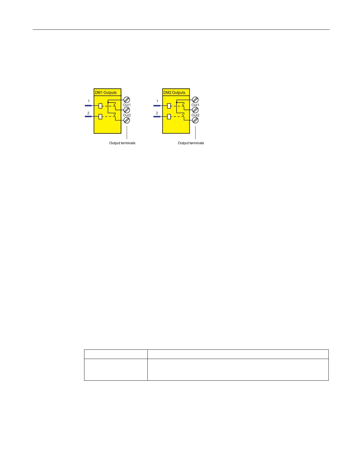
The following schematic shows the "DM Outputs" function blocks:
Figure 4-49 Schematic of the "DM1 Outputs" / "DM2 Outputs" function blocks
● Activation of the motor contactor in the motor feeder:
You can, for example, define which relay output is to be used for activating the main
contactor in the motor feeder. To do this, connect the desired relay output to the
respective "QE" contactor control of the control function.
● Activation of lamps for displaying operating states:
You can define, for example, which relay outputs are to be used for controlling the
lamps/LEDs that display the operating states of the motor (Fault, ON, OFF, FAST, SLOW
...). To do this, connect the desired relay output to the respective "QL..." lamp control of
the control function.
● Transfer of any other information, status information, warnings, faults, etc. to the relay
outputs.
In many cases, the outputs of the digital module will be connected to the QE outputs. By
referring to Table Active control stations, contactor controls, lamp controls and status
information for the control functions (Page 119), you can determine which QE outputs are
required for which control functions.
Table 4- 53 "DM1 / DM2 Outputs" settings
Outputs 1 to 2 Control of the "DM1 Outputs" and "DM2 Outputs" function blocks via any
signal (any socket, e.g. device inputs, PROFIBUS DP control bits, etc.
usually from the QE contactor controls.)
Defaults depend on the selected application (template): See Chapter Application selection,
settings and definitions of control functions (Page 66).

 Loading...


