Parameters
4.8 Logic modules
SIMOCODE pro - Parameterize
Operating Manual, 04/2017, A5E40507630002A/RS-AA/001
251
Non-volatile elements
Description
Non-volatile elements behave like signal conditioning. However, these output signals are
retained after a power supply failure.
If an input signal is pending, the non-volatile element issues an output signal according to
the selected type:
● Non-inverting
● Inverting
● Edge rising with memory
● Edge falling with memory
You can set the output response.
The non-volatile element consists of
● two plugs (input and reset)
● one logic component
● one socket
The following are available:
● two non-volatile elements (1 to 2) for the SIMOCODE pro C and SIMOCODE pro S basic
units
● four non-volatile elements 1 to 4 for the SIMOCODE pro V basic units
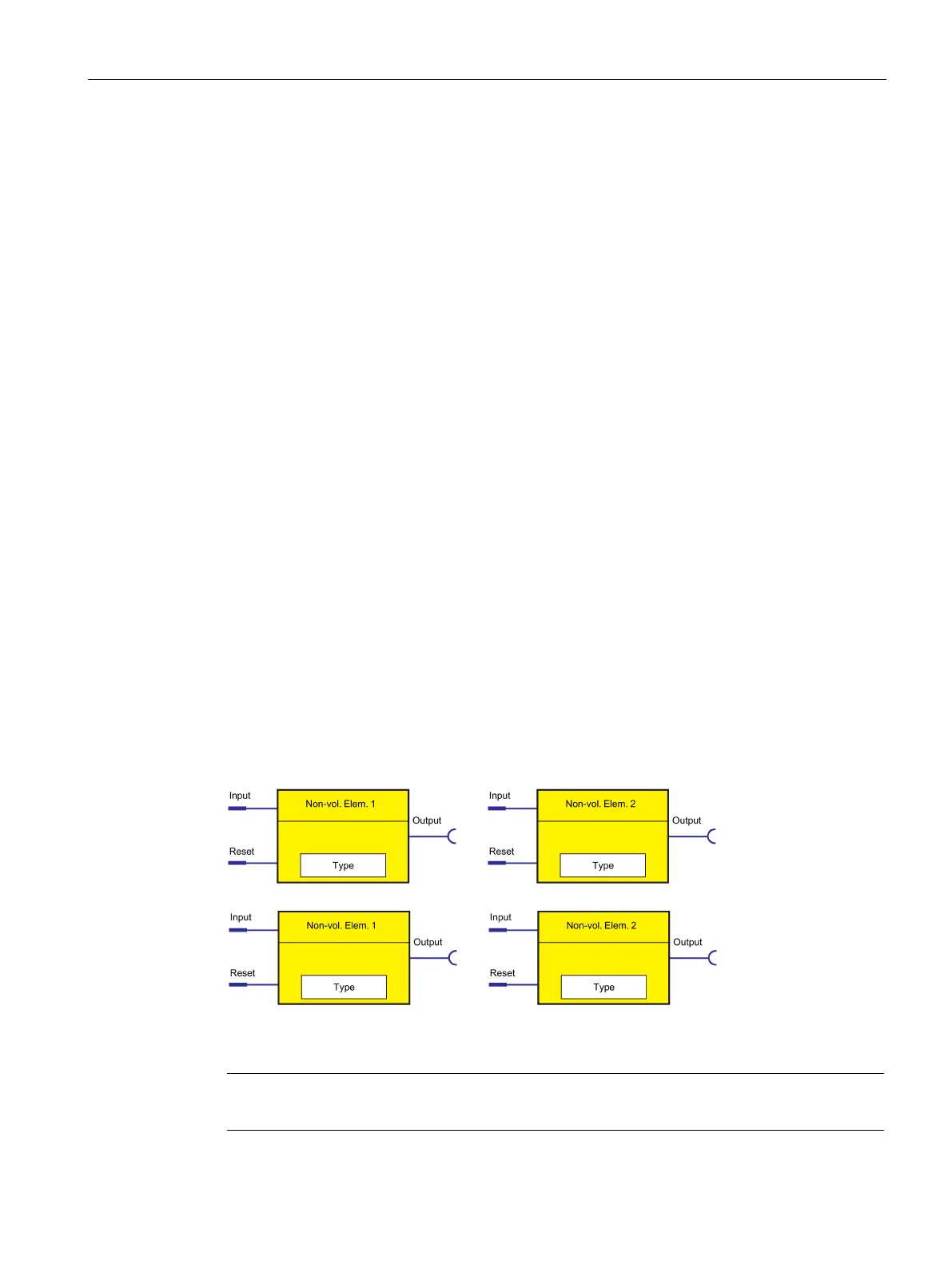
The following schematic shows the "Non-volatile element" logic modules:
Figure 4-101 "Non-volatile Element" logic modules
always 0 if a reset is pending.

 Loading...


