Parameters
4.8 Logic modules
SIMOCODE pro - Parameterize
268 Operating Manual, 04/2017, A5E40507630002A/RS-AA/001
Settings Analog Multiplexer
Table 4- 101 Settings Analog Multiplexer
Control signal S1 to S4 Activation by any signal (any sockets, e.g. device inputs, control bits from
the communication bus, etc.)
Input 1 to 4 Any analog value or "Fixed level"
Output value according to panel (see below)
Any analog value; range: 0 to 65535
Table 4- 102 Analog multiplexer panel
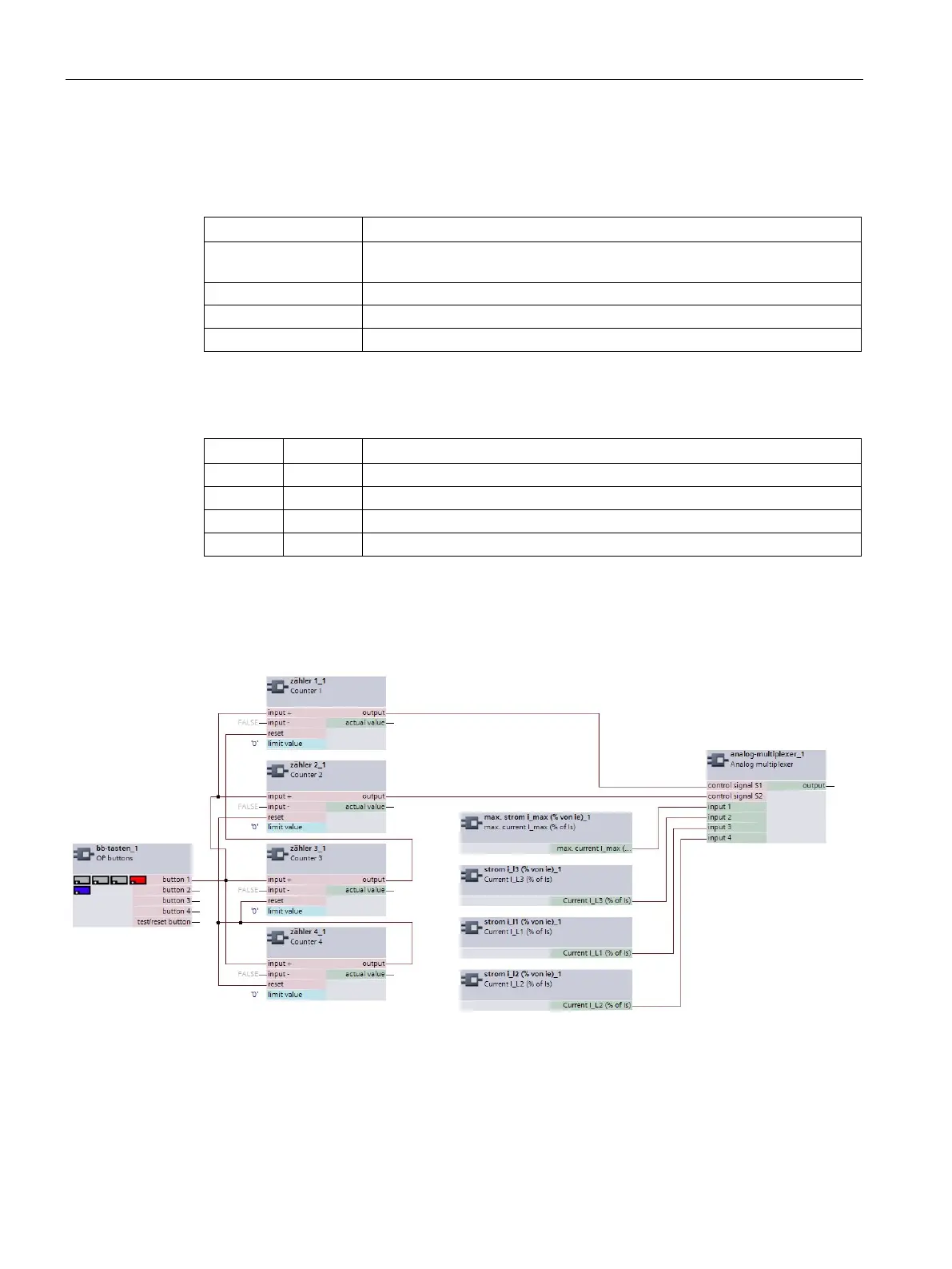
Analog multiplexer example
Pressing an operator panel button multiple times will output the maximum motor current and
the three phase currents one after the other (e.g., via the output of the analog module):
Figure 4-114 Analog multiplexer example
● Pressing the OP button 1x: Phase current IL1
● Pressing the OP button 2x: Phase current IL2
● Pressing the OP button 3x: Phase current IL3
● Pressing the OP button 4x: Maximum motor current I_max.

 Loading...


