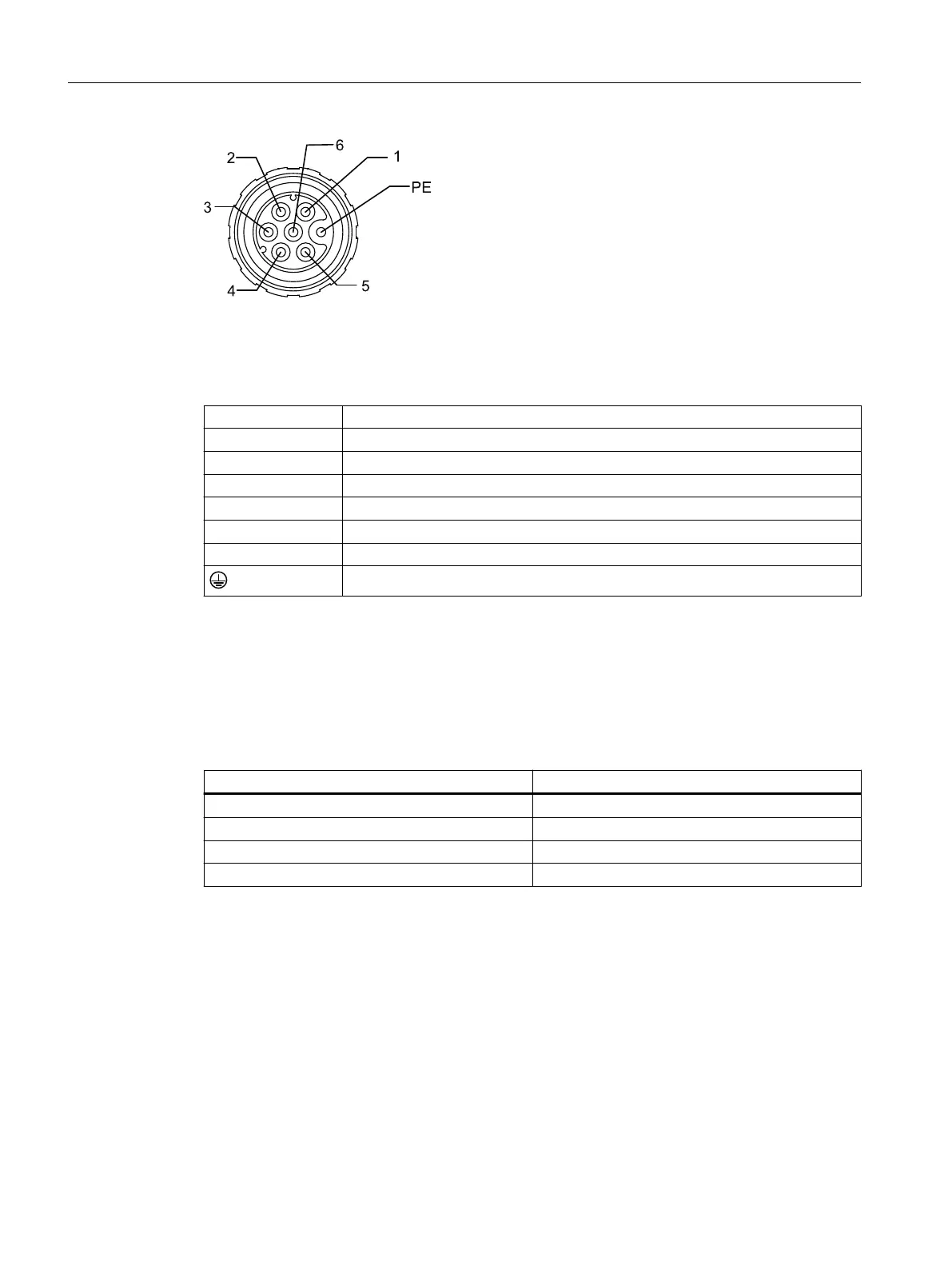
Figure6-13 Pin conguration, M17 signal connector
Table 6-4 PIN assignment, M17 signal connector
PIN Interface
1 -1R2: -KTY or Pt1000
2 +1R1: +KTY or Pt1000
3 1TP1: PTC 130°C
4 1TP2: PTC 130°C
5 2TP1: PTC 150°C *)
6 2TP2: PTC 150°C *)
PE
*) PTC150°C, optional in conjunction with KTY84
6.2.4 Power connection
Table 6-5 Conductor assignment for power cables with open conductor ends
Color/identication Connection
green/yellow PE
black / U / L1 / C / L+ U
black / V / L2 V
black / W / L3 / D / L- W
Cable protection for motors connected in parallel electrically
For the following congurations, you require a circuit breaker for each motor as conductor
protection:
• Several motors are connected in parallel to one Motor Module.
• The current-carrying capacity of the feeder cable cross-section is less than the rated current
of the Motor Module.
Connection
6.2Electrical connection
1FW6 built-in torque motors
100 Operating Instructions, 09/2022, A5E52220812B AA
 Loading...