3.1.8 Vibration response
The vibration response of build-in motors in operation essentially depends on the machine
design and the application itself.
As a result of an unfavorable machine design, conguration or system settings, resonance
points can be excited, so that vibration severity levelA according to EN6003414 is not
reached.
Excessive vibration caused by resonance eects can frequently be avoided by making suitable
settings. Contact Application & Mechatronic Support Direct Motors if you require help in
applying remedial measures. You can nd contact data in the Introduction under "Technical
Support".
3.2 Derating factors
For installation altitudes more than 2000m above sea level, reduce the voltage stress of the
motors according to the "Factors to reduce the maximum DC link voltage" table (reciprocal
values from EN 60664‑1 Table A.2).
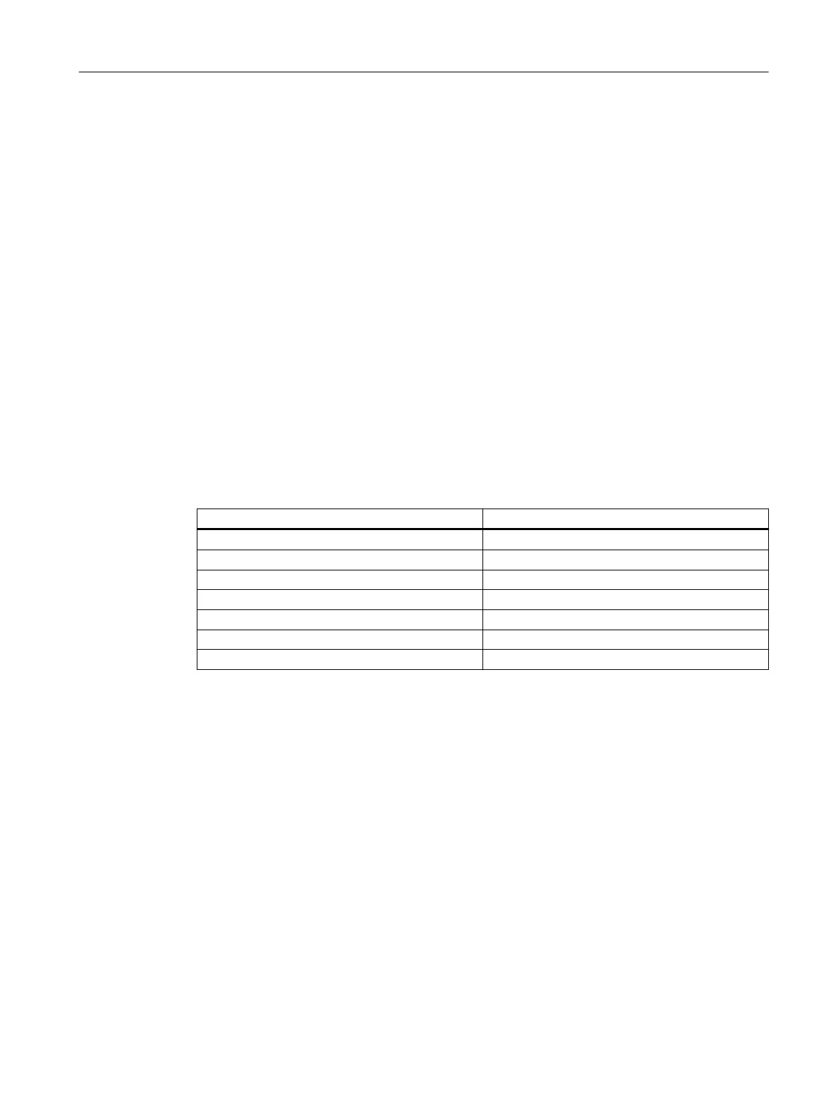
Table 3-3 Factors to reduce the maximum DC link voltage
Installation altitude above sea level in m up to Factor
2000 1
3000 0.877
4000 0.775
5000 0.656
6000 0.588
7000 0.513
8000 0.444
Reducing the DC link voltage reduces the converter output voltage. The operating range in
the M‑n diagram is also reduced.
You can nd the M‑n diagrams in the associated data sheet.
Operation in a vacuum is not permissible due to the low voltage strength and the poor
cooling.
3.3 Rating plate data
Technical data of the stator is provided on the rating plate (name plate). A second rating plate
is provided loose for the stator.
If, at a certain point in time, the stator and rotor are separated, then you must ensure that
the stator and rotor can be assigned to one another at a later point in time.
Description
3.3Rating plate data
1FW6 built-in torque motors
Operating Instructions, 09/2022, A5E52220812B AA 37
 Loading...