Frame size 5° electrical corresponds to mechanical 360° electrical corresponds to mechanical
1FW6230 0.1020° 7.35°
1FW6290 0.1190° 8.57°
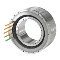
More information about coupled motors is provided in the Conguration Manual "SIMOTICS
T-1FW6 built-in torque motors for SINAMICS S120".
5.9 Checking the work performed
Checking the mounting work
After installation has been completed, check that the rotor can freely rotate. Note that with
short-circuited motor phases, the rotor is dicult to turn - even if no mechanical resistance is
otherwise present.
Before moving the rotor, remove all tools and objects from the area of the rotor and air gap.
WARNING
Risk of electric shock
A voltage is induced in the stator when the rotor rotates. You can get an electric shock when
touching the terminals, the open cable ends or the plug connector contacts.
• Correctly connect the motor power cables.
Alternatively:
Insulate the plug connector contacts or terminals and conductors of open cable ends before
you rotate the rotor.
• The mounted rotary axes must always be able to move without hindrance.
Examples of axes that cannot necessarily be checked by hand:
– Large axes with a high friction torque
– Blocking in a current-free state
– Uneven weight forces
WARNING
Danger if an axis moves in an uncontrolled manner.
There is a risk that the axis moves in an uncontrolled fashion if you release the locking
or brake when the axis is de-energized and not subject to closed-loop control.
• Carefully ensure that nobody is in the hazard zone.
• All cables must be routed and secured in such a way that they cannot be bent, pressed against
rotating parts or damaged in any other way.
• Coolant supply ducts must be easily accessible and the coolant must be allowed to ow freely.
Installation
5.9Checking the work performed
1FW6 built-in torque motors
82 Operating Instructions, 09/2022, A5E52220812B AA
 Loading...