Operator control (hardware)
2.3 7-segment and LED displays
SIMOTION D4x5-2
44 Manual, 02/2012
2.3 7-segment and LED displays
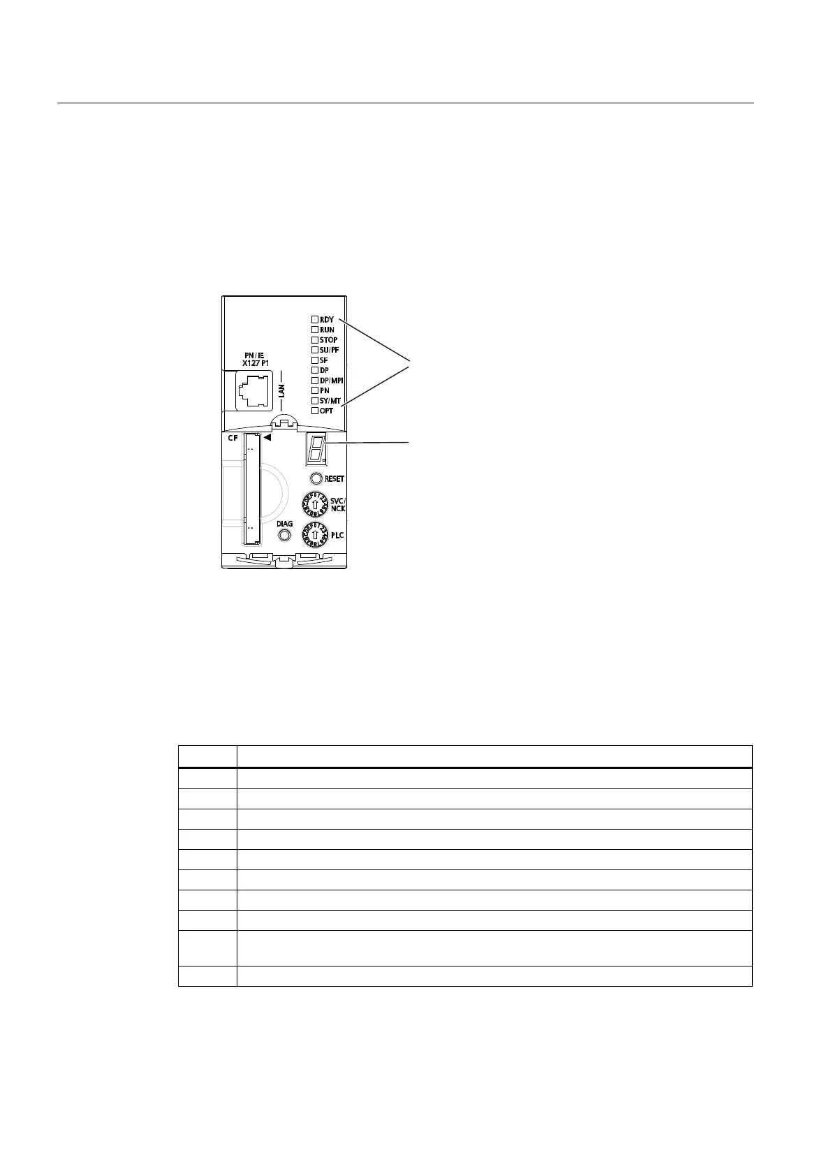
Arrangement of the displays
The front side of the SIMOTION D4x5-2 has ten LED displays arranged arranged vertically in
one row. There is also a 7-segment display below the blanking cover.
/('GLVSOD\V
[
VHJPHQWGLVSOD\
Figure 2-4 7-segment and LED display on the SIMOTION D4x5-2
Meaning of the LED displays
This table describes the LEDs and their meaning. The PN and
SY
LEDs have no function
for SIMOTION D4x5-2 DP.
Table 2- 5 Error and status displays
LED Meaning
RDY Operating states of SIMOTION D incl. SINAMICS Integrated.
RUN User program is running
STOP No user program is running. The technology packages are not active
SU/PF The technology packages are active. The user program is not active
SF An error state of the SIMOTION D4x5-2
DP State of the PROFIBUS DP interface
DP/MPI State of the PROFIBUS DP/MPI interface
PN State of the onboard PROFINET IO interface (X150)
SY/MT - Synchronization status (SY) of the onboard PROFINET IO interface (X150)
- Maintenance status (MT) of the D4x5-2 (currently without function)
OPT State of the option module (if available).

 Loading...


