Interfaces
3.9 Measuring sockets
SIMOTION D4x5-2
70 Manual, 02/2012
3.9 Measuring sockets
Application
The measuring sockets X141 (T0, T1 and T2) are on the lower side of the module and are
used to output analog signals. Any interconnectable signal can be output via SINAMICS on
every measuring socket on the control unit.
Interface assignment
Table 3- 19 Measuring sockets T0, T1, T2
Socket Function Technical specifications
T0 Measuring socket 0
T1 Measuring socket 1
T2 Measuring socket 2
7
7
0
7
M Ground
Voltage: 0 V to 5 V
Resolution: 8 bits
Load current: Max. 3 mA
Continuous short-circuit-proof
Reference potential is G terminal
The measuring sockets are suited for multiple-spring wire connectors with a diameter of 2 mm.
Note
The measuring sockets support commissioning and diagnostic functions. Connection for
normal operation is not permitted.
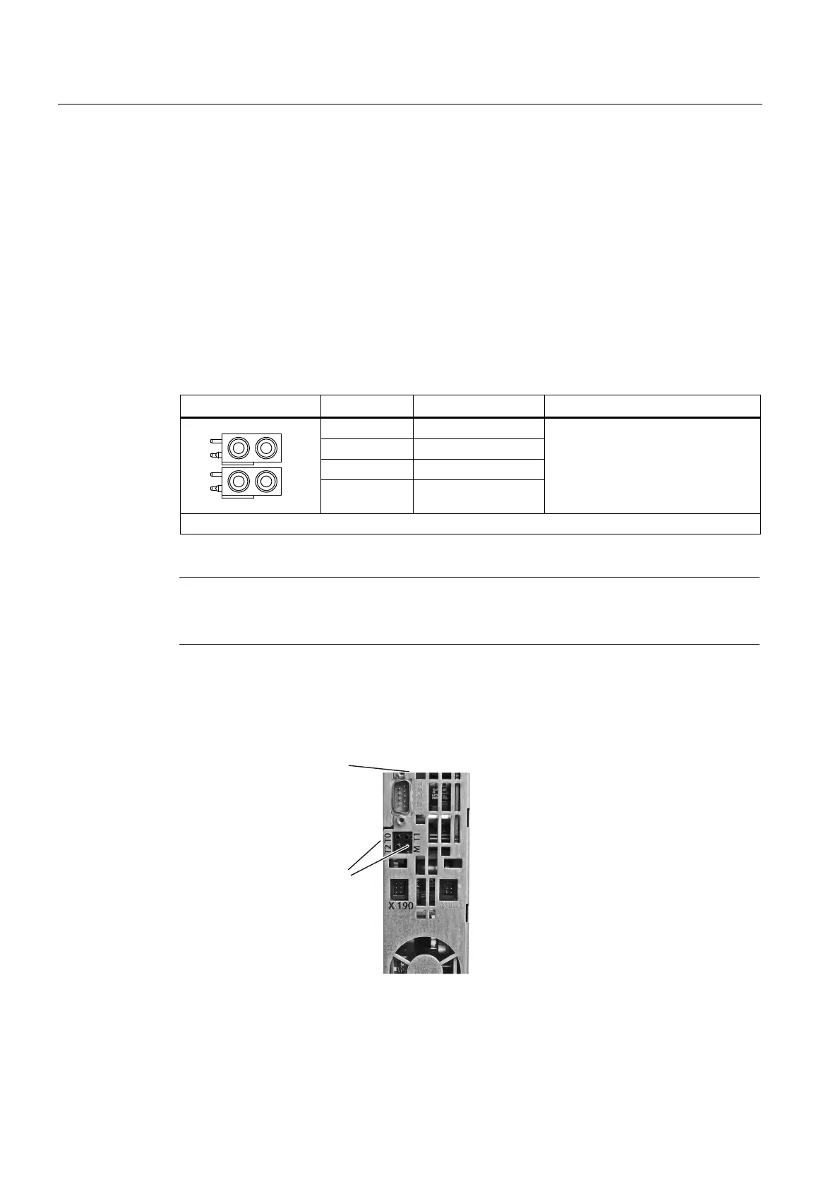
Measuring socket position
)URQWRIWKHFRQWUROXQLW
0HDVXULQJVRFNHWV
x 191
Figure 3-10 Measuring socket position

 Loading...


