6 - 25
6 General Repair
6B Hand Controls Repair
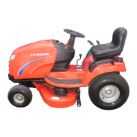
Figure B–19. Loosen V-Pulley
3. See Figure B–19. Note the position of the belt stop
relative to the v-pulley, and then loosen the lock nut
that secures the v-pulley to the idler. Slide the drive
belt out of the gap between the pulley and belt stop.
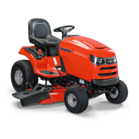
Figure B–20. Remove Clip Ring And Idler Arm
Assembly
4. See Figure B–20. Slide the clip ring out of the groove
on the pivot shaft, and remove the idler arm assem-
bly from the unit by pulling it straight out and off the
shaft. (See Foot Controls section 6C for
specific idler arm assemblies and components used
on various models.)
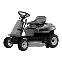
Figure B–21. Lockout Lever/Shift Pivot Assembly
5. See Figure B–21. Remove the hex nut that secures
the lockout lever to the shift pivot assembly. (See
Figure B–21 for complete hardware details.)
6. Lift the rear shift rod off the screw threads and move
it aside, and slide the lockout lever off the pivot shaft.
Belt Stop
Clip Ring
Lockout
Lever
Shift Pivot
Rear Shift Rod
 Loading...