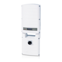
Figure 36: The RJ45 Ethernet connection
7. Fortheswitch/routerside,useapre-crimpedcableoruseacrimpertoprepareanRJ45
communicationconnector:InserttheeightwiresintotheRJ45connectorinthesameorderasabove
(Figure35).
8. ConnectthecableRJ45connectortotheRJ45portoftheEthernetswitchorrouter.
Youcanconnectmorethanoneinvertertothesameswitch/routerortodifferentswitches/routers,
asneeded.EachinvertersendsitsmonitoreddataindependentlytotheSolarEdgemonitoring
platform.
9.
TheinverterisconfiguredbydefaulttoLAN.Ifreconfigurationisrequired:
a. MakesuretheON/OFFswitchisOFF.
b. TurnONtheACtotheinverterbyturningONthecircuitbreakeronthemaindistributionpanel.
c. TurnONtheStorEdgeConnectionUnit.
WARNING!
ELECTRICAL SHOCK HAZARD. Do not touch uninsulated wires when the inverter cover is
removed.
RISQUE D’ÉLECTROCUTION, ne touchez pas les fils non isolés lorsque le couvercle de
l'onduleur est retiré.
d. Usetheinternaluserbuttonstoconfiguretheconnection,asdescribedinCommunicationon
page58.
NOTE
If your network has a firewall, you may need to configure it to enable the connection to the
following address:
l Destination Address: prod.solaredge.com
l TCP Port: 22222 (for incoming and outgoing data)
10. Verifytheconnection,asdescribedinVerifyingtheConnectiononpage77.
Creating an RS485 Bus Connection
TheRS485optionenablescreatingabusofconnectedinverters,consistingofupto31slaveinvertersand
1masterinverter.Usingthisoption,invertersareconnectedtoeachotherinabus(chain),viatheir
RS485connectors.Thefirstandlastinvertersinthechainmustbeterminated.
RS485wiringspecifications:
l Cabletype:Min.3-wireshieldedtwistedpair(a4-wirecablemaybeused)
l Wirecross-sectionarea:0.2-1mm²/24-18AWG(aCAT5cablemaybeused)
SolarEdge StorEdge Installation Guide MAN-01-000262-1.2
74
Creating an RS485 Bus Connection
 Loading...