10.
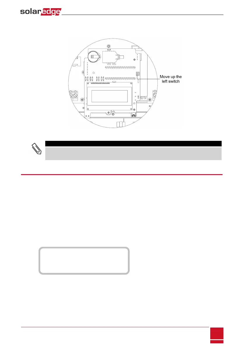
TerminatethefirstandlastSolarEdgedevice(inverter/Controlandcommunicationgateway,etc.)in
thechainbyswitchingaterminationDIP-switchinsidetheinvertertoON(movetheswitchup).The
switchislocatedonthecommunicationboardandismarkedSW7.
Figure 40: RS485 termination switch
NOTE
Only the first and last SolarEdge devices in the chain should be terminated. The other inverters in
the chain should have the termination switch OFF (down position).
Verifying the Connection
Afterconnectingandconfiguringacommunicationoption,performthefollowingstepstocheckthat
theconnectiontothemonitoringserverhasbeensuccessfullyestablished.
1. Closetheinvertercover:Attachtheinvertercoverandsecureitbytighteningthescrewswitha
torqueof9.0N*m/6.6lb.*ft.Forpropersealing,firsttightenthecornerscrewsandthenthetwo
centralscrews.
2. TurnONtheACtotheinverterbyturningONthecircuitbreakeronthemaindistributionpaneland
turningontheStorEdgeConnectionUnit.
3. WaitfortheinvertertoconnecttotheSolarEdgemonitoringplatform.Thismaytakeuptotwo
minutes.
AstatusscreensimilartothefollowingappearsontheLCDpanel:
V a c [ V ] V d c [ V ] P a c [ w ]
2 4 0 . 7 1 4 . 1 0 . 0
P _ O K : 0 0 0 / 0 0 0 < S _ O K >
- - - - - - - - - - - - - - - O F F
S_OK:IndicatesthattheconnectiontotheSolarEdgemonitoringplatformissuccessful.IfS_OKisnot
displayed,referto"Troubleshooting"onpage87.
Chapter 8: Setting Up Communication to the Monitoring Platform
SolarEdge-StorEdge Installation Guide MAN-01-00262-1.2
77
 Loading...