5-35
DCR-TRV240/TRV340
2-2. DIGITAL8 MODE
Note1: Before performing the adjustments, check the data of page: 0,
address: 10 is “00”. If not, set data: 00 to this address.
Note2: < >: DCR-TRV240, [ ]: DCR-TRV340
2-2-1. HOW TO ENTER RECORD MODE WITHOUT
CASSETTE
1) Connect the adjustment remote commander to the LANC jack.
2) Turn the HOLD switch of the adjustment remote commander
to the ON position.
3) Close the cassette compartment without the cassette.
4) Select page: 3, address: 01, and set data: 0C, and press the
PAUSE button of the adjustment remote commander.
(The mechanism enters the record mode automatically.)
Note: The function buttons becomes inoperable.
5) To quit the record mode, select page: 3, address: 01, set data:
00, and press the PAUSE button. (Whenever you want to quit
the record mode, be sure to quit following this procedure.)
2-2-2. HOW TO ENTER PLAYBACK MODE WITHOUT
CASSETTE
1) Connect the adjustment remote commander to the LANC jack.
2) Turn the HOLD switch of the adjustment remote commander
to the ON position.
3) Close the cassette compartment without the cassette.
4) Select page: 3, address: 01, and set data: 0B, and press the
PAUSE button.
(The mechanism enters the playback mode automatically.)
Note: The function buttons becomes inoperable.
5) To quit the playback mode, select page: 3, address: 01, set data:
00, and press the PAUSE button. (Whenever you want to quit
the playback mode, be sure to quit following this procedure.)
2-2-3. OVERALL TAPE PATH CHECK
1. Recording of the tape path check signal
1) Clean the tape running side (tape guide, capstan shaft, pinch
roller).
2) Connect the adjustment remote commander to the LANC jack.
3) Turn the HOLD switch of the adjustment remote commander
to the ON position.
4) Set to the camera recording mode.
5) Select page: 3, address: 1C, set data: 5D, and press the PAUSE
button of the adjustment remote commander.
6) Record for several minutes.
7) Release the camera recording mode.
8) Select page: 3, address: 1C, set data: 00, and press the PAUSE
button.
2. Tape path check
1) Clean the tape running side (tape guide, capstan shaft, pinch
roller).
2) Connect the adjustment remote commander to the LANC jack.
3) Turn the HOLD switch of the adjustment remote commander
to the ON position.
4) Connect an oscilloscope to VC-276 board CN1108 via the CPC-
13 jig (J-6082-443-A).
Channel 1: VC-276 board, CN1108 Pin qh (Note)
External trigger: VC-276 board, CN1108 Pin qd
Note: Connect a 75Ω resistor between Pins qh of CN1108 and 6
(GND).
5) Select page: <2>[7], address: <4D>[62], and set data: <40>[01].
(Note2)
6) Playback the tape path check signal.
7) Select page: 3, address: 26, and set data: 31.
8) Select page: 3, address: 33, and set data: 08.
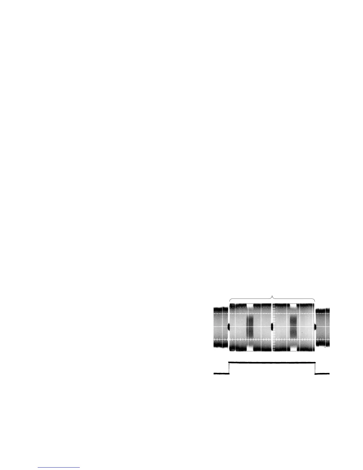
9) Check that the oscilloscope RF waveform is flat at the entrance
and exit.
If not flat, perform “2-1-2. TAPE PATH ADJUSTMENT” of
“2-1. HI8/STANDARD 8mm MODE”.
10) Select page: 3, address: 26, and set data: 00.
11) Select page: 3, address: 33, and set data: 00.
12) Select page: <2>[7], address: <4D>[62], and set data: 00.
(Note2)
Must be flat
Pin qd
Pin qh
Fig. 5-2-2.
 Loading...