2-2
DCR-TRV240/TRV340
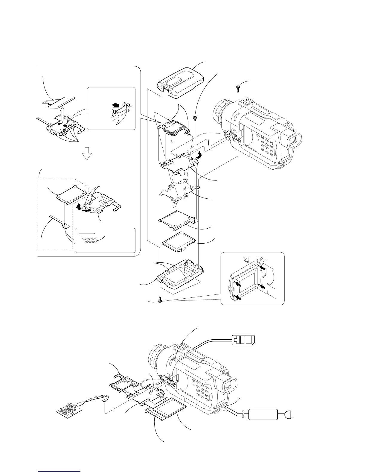
NOTE: Follow the disassembly procedure in the numerical order given.
2-1. LCD UNIT, PD-160 BOARD
PD-160
Board
PD-160
Board
2
Two claws
4
Two claws
qa
Claw
A
5
1
Four tapping screws (M1.7
×
5)
qd
P frame (2)
9
Back light (Cold cathode fluorescent tube)
6
Two tapping screws
(B1.7
×
6)
q;
P screw (M1.7
×
2.5)
3
P cabinet (C (2))
7
P cabinet (M) (2) assembly
qs
Remove the PD-160 board
in the direction of the arrow
A
.
8
Liquid crystal indicator module
REMOVING THE BACK LIGHT
[PD-160 BOARD SERVICE POSITION]
Back light (Cold cathode fluorescent tube)
Adjustment remote
commander (RM-95)
PD-160 board
Multi CPC jig
(J-6082-311-A)
Liquid crystal indicator module
Indication LCD block assembly
LANC jack
CN5502
DC IN
AC POWER
ADAPTOR
AC I
4
Two claws
2
Four claws
Two claws
B
9
Back light
C
D
7
Remove
the two
solderings.
6
LCD holder
3
Remove the indication LCD block assembly
in the direction of the arrow
B
.
5
Remove the back light, flexible flat cable
(FP-414) in the direction of the arrow
C
to
D
.
1
Push this point to
remove the two
claws.
8
FP-414
flexible board
 Loading...