2-1
SECTION 2
DISASSEMBLY
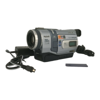
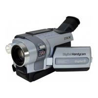
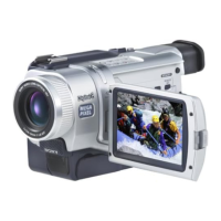
DCR-TRV240/TRV340
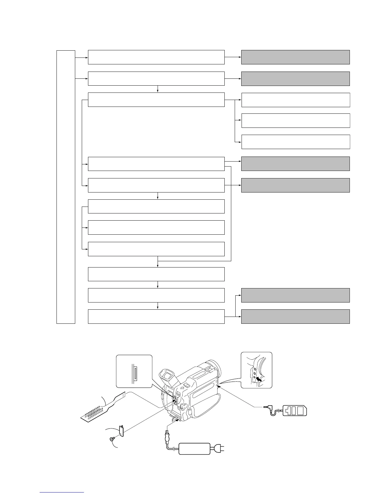
The following flowchart shows the disassembly procedure.
DCR-TRV240/TRV340
2-1. LCD unit, PD-160 board
PD-160 board service position
2-2. Front panel section, SI-032 board
SI-032 board service position
LB-076 board service position
CD-357 board service position
2-3. Cabinet (R) section
2-4. Lens section, CD-357 board
2-14. Hinge section
2-12. Control switch block (CF-2500)
2-13. Control switch block (FK-2500)
2-5. EVF section, LB-076 board
2-6. Battery panel section, Battery terminal board
2-7. Memory Stick 10P Connector (Memory stick model)
2-8. Control switch block (SS-1380)
2-9. Cabinet (L) section, CS frame assembly (25)
2-10. VC-276 board
2-11. Mechanism deck
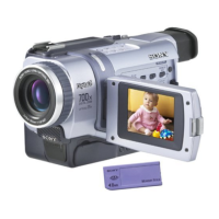
Memory stick model : DCR-TRV340
Service position to check the VTR section
Service position to check the camera section
[CONNECTION OF EQUIPMENTS]
AC IN
AC power
adaptor
MI screw
(M2
×
4) (H)
Remove the
CPC lid (BT)
CN1108
20
1
Adjustment remote
commander (RM-95)
CPC-13 jig
(J-6082-443-A)
 Loading...