5-50
DCR-TRV240/TRV340
3-5. AUDIO SYSTEM ADJUSTMENTS
Note: Before performing the adjustments, check the data of page: 0,
address: 10 is “00”. If not, set data: 00 to this address.
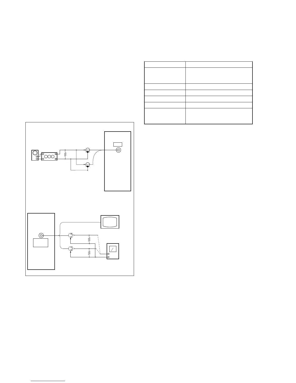
[Connecting the measuring instruments for the audio]
Connect the audio system measuring instruments in addition to the
video system measuring instruments as shown in Fig. 5-3-10.
[Adjustment Procedure]
1) Hi8/Standard8 AFM BPF f0 adjustment
2) Hi8/Standard8 AFM 1.5MHz deviation adjustment
3) Hi8/Standard8 AFM 1.7MHz deviation adjustment
4) Digital8 playback level check
5) Overall level characteristics check
6) Overall distortion check
7) Overall noise level check
8) Overall separation check
1. Hi8/Standard8 AFM BPF f
0 Adjustment
(VC-276 board)
Sets the BPF passing frequency of IC5701 so that the AFM signal
can separate from the playback RF signal properly. If deviated. the
mono/stereo mode will be differentiated incorrectly, and noises and
distortions will increase during high volume playback.
Mode Playback
Signal Hi8/Standard8 alignment tape:
For BPF adjustment
(WR5-11NS)
Measurement Point AUDIO/VIDEO jack left or right
Measuring Instrument Distortion meter
Adjustment Page C
Adjustment Address 4E
Specified Value The Main and Sub channel distortion
rate should be almost the same (within
± 1%) and minimum.
Note: The data of page: 0, address: 10 must be “00”.
Adjusting method:
1) Select page: 0, address: 01, and set data: 01.
2) Set the Hi-Fi SOUND switch (menu display) to “2”.
3) Select page: C, address: 4E, change the data and minimize the
distortion rate.
4) Press the PAUSE button.
5) Set the Hi-Fi SOUND switch (menu display) to “1”.
6) Select page: C, address: 4E, change the data and minimize the
distortion rate.
7) Press the PAUSE button.
8) Repeat steps 2) to 7) and set the data of address: 4E so that the
distortions rates when the Hi-Fi SOUND switch is set to “2”
and set to “1” respectively are almost the same and minimum.
9) Press the PAUSE button.
10) Select page: 0, address: 01, and set data: 00.
11) Set the Hi-Fi SOUND switch to “STEREO”.
Fig. 5-3-10.
Recording (Camera mode)
Audio oscillator
Attenuator
600 Ω
Left
Right
Main unit
MIC
600 Ω: 270 Ω (1-249-410-11) + 330 Ω (1-249-411-11)
Main unit
AUDIO/
VIDEO
Left (White)
Right
47k Ω
47k Ω
Video (Yellow)
TV monitor
Audio level meter
or Distortion meter
47k Ω (1-249-437-11)
Playback
(Red)
 Loading...