5-39
DCR-TRV240/TRV340
3-1-5. Alignment Tape
The following table lists alignment tapes which are available.
Use the tape specified in the signal column for each adjustment. If
the type of tape to be used for checking operations is not specified,
use whichever type.
Digital8 alignment tape
Name Usage
SW/OL standard Switching position adjustment
(WR5-2D)
Audio operation check Audio system adjustment
(WR5-3ND),
System operation check
Operation check
(WR5-5ND)
Hi8/standard 8 alignment tape
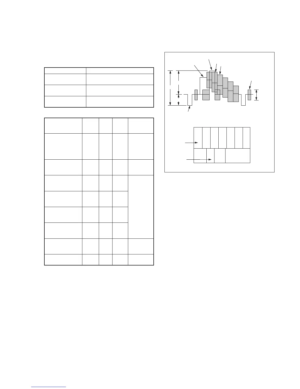
Fig. 5-3-3. Color Bar Signal of the Alignment Tape
3-1-6. Input/output Level and Impedance
Video input/output
Special stereo minijack, 1Vp-p, 75Ω, unbalanced, sync negative
S video input/output
4-pin mini DIN
Luminance signal: 1Vp-p, 75Ω, unbalanced, sync negative
Chrominance signal: 0.286Vp-p, 75Ω, unbalanced
Audio input/output
Special stereo minijack:
Input: –7.5dBs, input impedance more than 47kΩ
Output:–7.5dBs, (at load impedance 47kΩ), impedance less
than 2.2kΩ
Tape type
ME ......... Particle type metal tape
MP .......... Evaporated type metal tape
White
(75%)
White
(100%)
Q
I
Black
Cyan
Yellow
Green
Magenta
Red
Blue
Color bar signal waveform
Name
Tracking
WR5-1NP
Video frequency
characteristics
WR5-7NE
Operation check
(SP mode)
WR5-5NSP
Operation check
(SP mode)
WR5-8NSE
Operation check
(LP mode)
WR5-4NL
Operation check
(LP mode)
WR5-8NLE
AFM stereo
Operation check
WR5-9NS
BPF adjustment
WR5-11NS
Record
-ing
mode
Standard 8
Hi8
Standard 8
Hi8
Standard 8
Hi8
Standard 8
Standard 8
Tape
type
MP
ME
MP
ME
MP
ME
MP
MP
Tape
speed
SP
SP
SP
SP
LP
LP
SP
SP
Usage
Tape path
adjustment
Switching
position
adjustment
Frequency
characteristics
adjustment
Checking
operations
AFM stereo
Checking
operations
BPF
adjustment
Fig.5-3-3. shows the 75% color bar signals recorded on the alignment
tape.
Note: Measure using the VIDEO terminal (Terminated at 75Ω).
 Loading...