EasyManuals Logo

Sony DCR-TRV240 User Manual

Sony DCR-TRV240
180 pages
To Next Page IconTo Next Page
To Previous Page IconTo Previous Page
Page #67 background imageLoading...
Page #67 background image
2-7
DCR-TRV240/TRV340
2-6. BATTERY PANEL SECTION, BATTERY TERMINAL BOARD
6
Two MI screws
(M2
×
4) (H)
2
MI screw
(M2
×
4) (H)
5
MI screw
(M2
×
4) (H)
9
Battery panel
section
2
Ferrite
bead
1
Tape (A)
8
A
3
4
(Memory stick model) (TRV340)
7
Tapping screw
(M1.7
×
5)
3
FP-409 flexible
board (10P)
5
Strap sheet
metal (lower)
6
Battery terminal
board
4
Battery terminal
board (6P)
1
Jack lid
(2500)
REMOVING THE
BATTERY TERMINAL BOARD
A
2-7. MEMORY STICK 10P CONNECTOR (MEMORY STICK MODEL) (TRV340)
8
Memory stick 10p connector
7
MS holder
4
MS section
2
Two screws
(M1.7
×
2.5), p
1
Screw
(M1.7
×
2.5), p
3
6
Two screws
(M1.7
×
2.5), p
5
FP-409 flexible board
(10P)

Table of Contents

Questions and Answers:

Question and Answer IconNeed help?

Do you have a question about the Sony DCR-TRV240 and is the answer not in the manual?
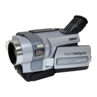
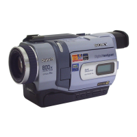
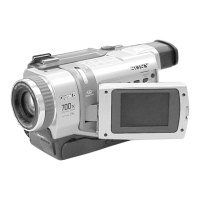
Sony DCR-TRV240 Specifications

General IconGeneral
Digital zoom700 x
Optical zoom25 x
Image stabilizerYes
Focal length range2.4 - 60 mm
Sensor typeCCD
Total megapixels0.8 MP
Optical sensor size1/6 \
Display diagonal2.5 \
Minimum illumination4 lx
Weight and Dimensions IconWeight and Dimensions
Depth101 mm
Width85 mm
Height206 mm

Related product manuals