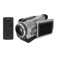
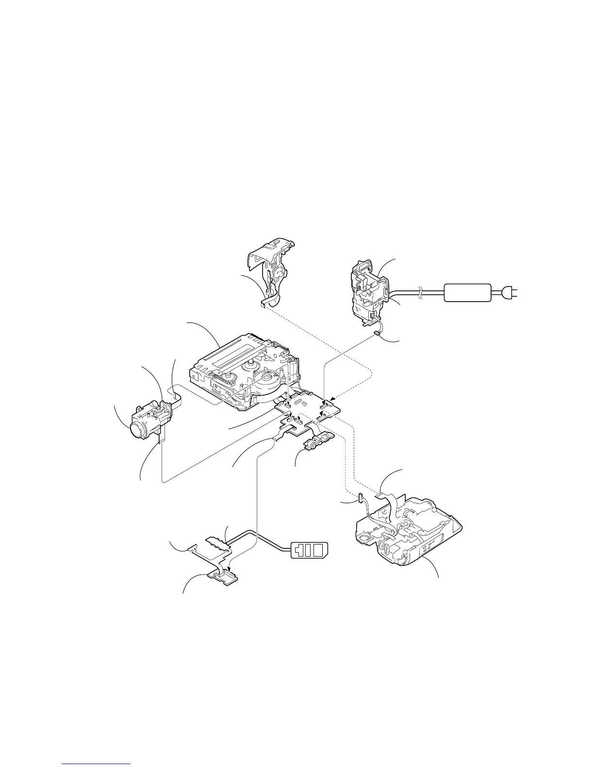
2-11
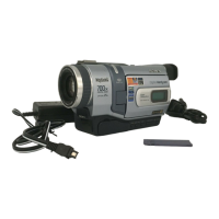
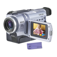
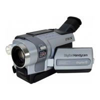
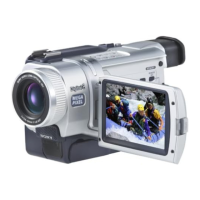
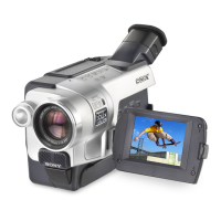
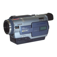
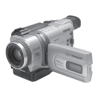
DCR-TRV240/TRV340
Adjustment remote
commander (RM-95)
AC IN
DC IN
AC POWER
ADAPTOR
FP-406 flexible
board (30P)
Control switch block
(SS-1380) (12P)
Mechanism deck
FP-410
flexible board
FP-161 flexible
board (16P)
Iris flexible
assembly (24P)
Battery panel
section
Battery terminal
board (6P)
VC-276
board
Lens section
LANC
jack
SI-032 board
VC-276
Board
CD-357 board
Cabinet (R) block section
Control switch block
(CF-2500) (22P)
Harness
(PD-117) (20P)
[SERVICE POSITION TO CHECK THE CAMERA SECTION]
Note : If the machine malfunctions (the operating mode changes by itself), connect the Cabinet (R) section.
Connection to Check the Camera Section
To check the camera section, set the camera to the “Forced camera power ON” mode.
When you want to operate to zoom and focus, use the controls on the remote commander (with the HOLD switch off).
Setting the “Forced Camera Power ON” mode
1) Select page: 0, address: 01, and set data: 01.
2) Select page: 0, address: 10, and set data: 00.
3) Select page: D, address: 10, set data: 01 and
press the PAUSE button of the adjustment remote
commander.
Exiting the “Forced Camera Power ON” mode
1) Select page: 0, address: 01, and set data: 01.
2) Select page: 0, address: 10, and set data: 00.
3) Select page: D, address: 10, set data: 00, and press
the PAUSE button of the adjustment remote
commander.
4) Select page : 0, address: 01, and set data: 00.
FP-411
flexible board
 Loading...