3-11 (E)
HXCU-100
3-4-4. VBS Signal Level Adjustment
Adjust the VBS signal level that is output from this unit using the color-bar signal.
Adjustment Procedure
Adjust the VBS signal level with VBS LEVEL of M05:ANALOG VIDEO2 in the MAINTENANCE
menu.
Equipment: SD waveform monitor
Test Point: VBS connector/SDI-97 board
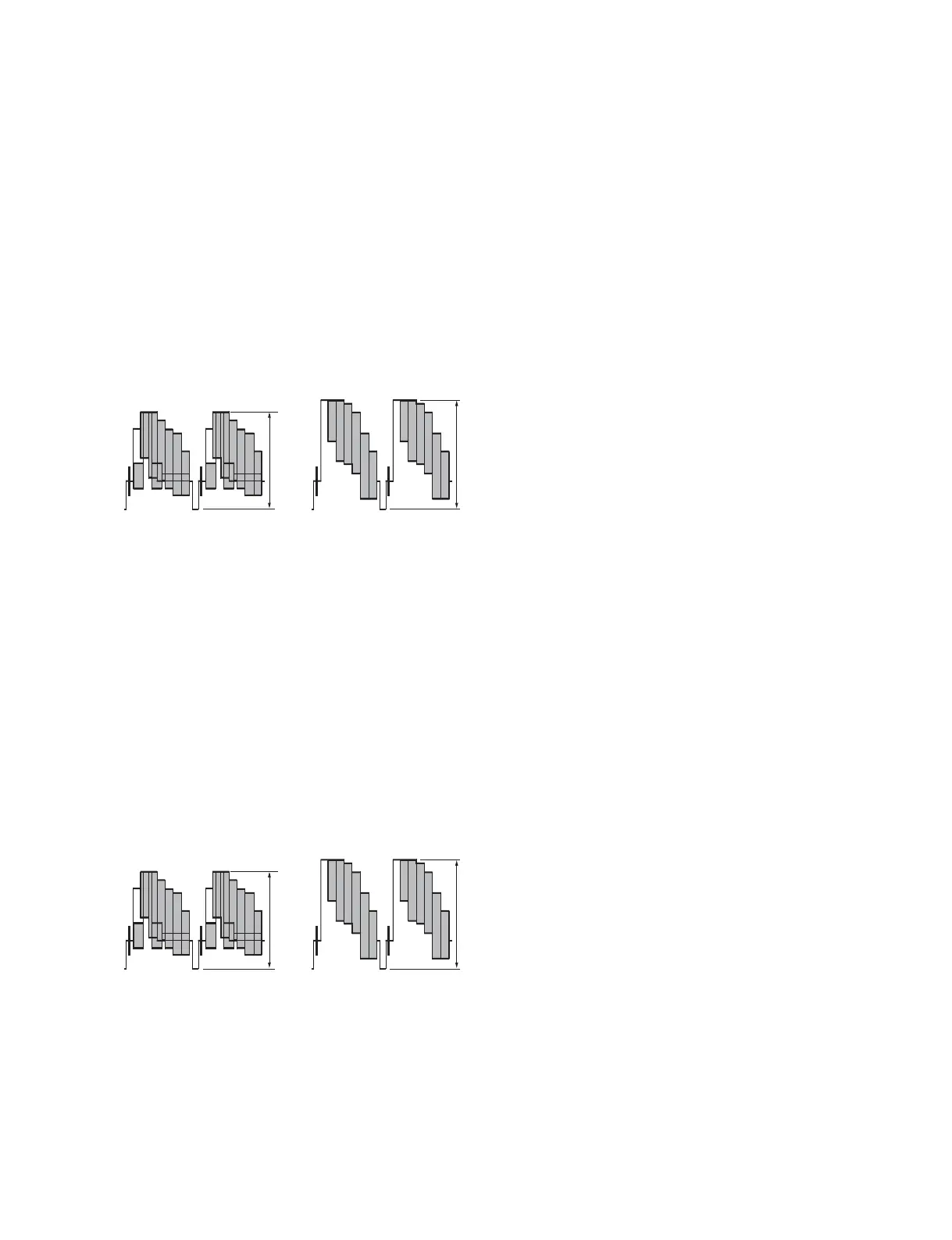
Specifi cation: A = 140 ?1 IRE (75 Z termination)
B = 1000 ?7 mV p-p (75 Z termination)
BA
NTSC
PAL
3-4-5. Waveform Monitor Signal Level Adjustment
The video output signal of the unit can be checked using the waveform monitor connected to the WF
connector. Adjust the WF output signal level using the color-bar signal.
WF Output Signal Level Adjustment Procedure
Adjust the WF output signal level with WF LEVEL of M05:ANALOG VIDEO2 in the MAINTENANCE
menu.
Equipment: SD waveform monitor
Test Point: WF connector/CN-3080 board
Specifi cation: A = 140 ?1 IRE (75 Z termination)
B = 1000 ?7 mV p-p (75 Z termination)
BA
NTSC
PAL
 Loading...