PARTS REPLACEMENT
– 41 –
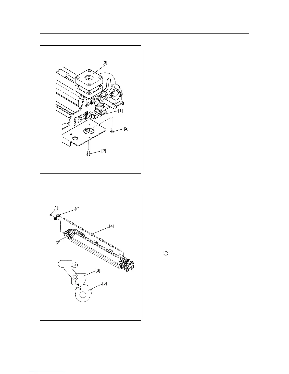
9. Carriage Motor Unit
(1) Remove
• Printer mechanism according to the procedure
described in item 3.
• Cord fastener binding the lead wires.
• Connector [1]
• Two screws [2]
• Carriage motor unit [3]
(2) Adjust
• Timing belt tension
Refer to item 2 of Chapter 3.
10. Bail Roller Shaft Unit
(1) Remove
• Upper case unit according to the procedure de-
scribed in item 1.
• Stop ring SE3 [1]
• Spring [2]
• Bail Lever L [3]
• Bail roller shaft unit [4]
Caution in assembly:
Align the ∆ mark on the bail lever L [3] with the
●● mark on the gear [5] to install the bail lever L
[3] .
 Loading...