PARTS REPLACEMENT
– 42 –
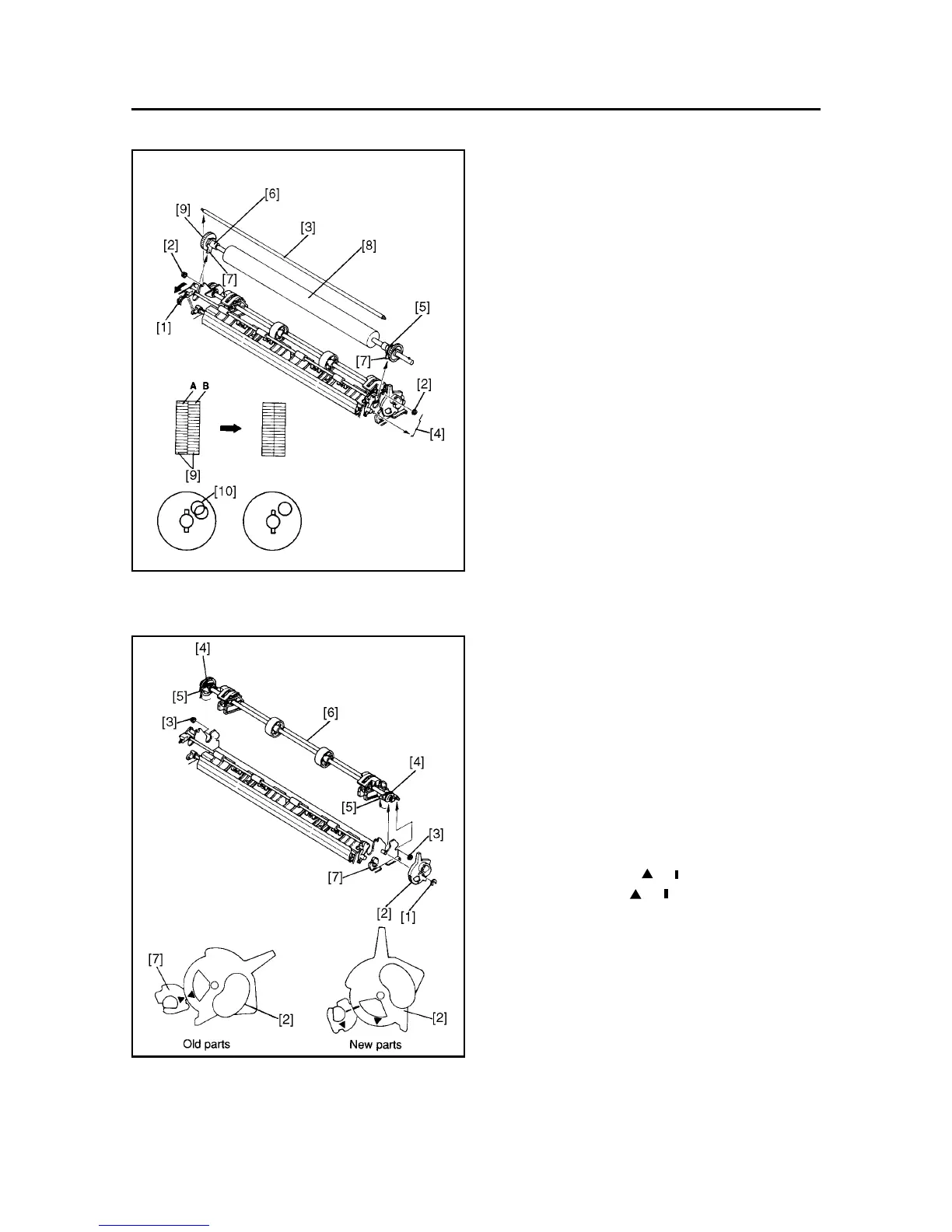
11. Platen Unit
(1) Remove
• Upper case unit according to the procedure de-
scribed in item 1.
(2) Move the bail lever [1] forward.
(3) Remove
• Two nuts [2]
• Tractor stay [3]
• Ground contact spring [4]
• Platen holder R [5]
• Platen holder L [6]
Lift the tabs [7] of platen holders R and L to allow
removal of platen holders R and L from the frame.
• Platen unit [8]
Caution in assembly:
When assembling the platen gear assembly [9] on
the idler gear, align the teeth of gear A and gear B
(be sure to align the holed [10] in the two gears.)
(4) Adjust
• Gap between print head and platen.
Refer to item 1 of Chapter 3.
12. Tractor Unit
(1) Remove
• Platen unit according to the procedure described
in item 11.
• Stop ring [1]
• Release lever [2]
• Two nuts [3]
• Two tractor bushings [4]
Lift the tab [5] of the tractor bush allow removal
of the tractor bush from the frame.
• Tractor unit [6]
Caution in assembly:
Aligen the mark ( or ) on the release lever [2],
with the mark ( or ) on the release gear [7] to
install the release lever [2].
 Loading...