K
Karen SnyderJul 29, 2025
What to do if printer mechanism needs replacement in Star Micronics Printer?
- EErin BrownJul 29, 2025
If you need to address the printer mechanism in your Star Micronics Printer, the solution is to replace it.
 Loading...
What to do if printer mechanism needs replacement in Star Micronics Printer?
If you need to address the printer mechanism in your Star Micronics Printer, the solution is to replace it.
| Brand | Star Micronics |
|---|---|
| Model | NX-1500 |
| Category | Printer |
| Language | English |
Identifies printer models and target markets.
Outlines the main sections and topics covered in the manual.
Lists the publication dates of different manual editions.
Core printer specifications including speed, paper feed, and character sets.
Describes the physical layout and components of the printer.
Explains the function of DIP switches for configuration.
Covers specifications, signals, and timing for parallel connectivity.
Details specifications, signals, and DIP settings for serial connectivity.
Overview of printer architecture and logic board functions.
Explains parallel and serial data input methods and handshake.
Details editing, printing, and overall printer operation flow.
Explains operation of carriage, paper feed motors, and print head control.
Describes print head, carriage, ribbon feed, and paper feed mechanisms.
Explains the function of various printer sensors.
Procedure for measuring and adjusting the print head gap.
Method for adjusting the timing belt tension.
Steps to adjust the home position detector.
Important safety and assembly notes before servicing.
Steps to remove and replace the printer's upper case.
Procedure for replacing the control panel board.
Steps for removing and replacing the main logic board.
Instructions for replacing the fuse board and individual fuses.
Procedure to remove, replace, and adjust the print head.
Guides for replacing paper feed and carriage motor units.
Steps for replacing bail roller shaft and platen units.
Procedure for removing and replacing the tractor unit.
Instructions for cleaning the printer's exterior and interior.
Outlines daily and periodic checks for printer upkeep.
Recommends lubricants, methods, and frequency for printer lubrication.
Identifies specific points requiring lubrication with diagrams.
General strategy for diagnosing and repairing printer issues.
A chart guiding unit replacement based on symptoms.
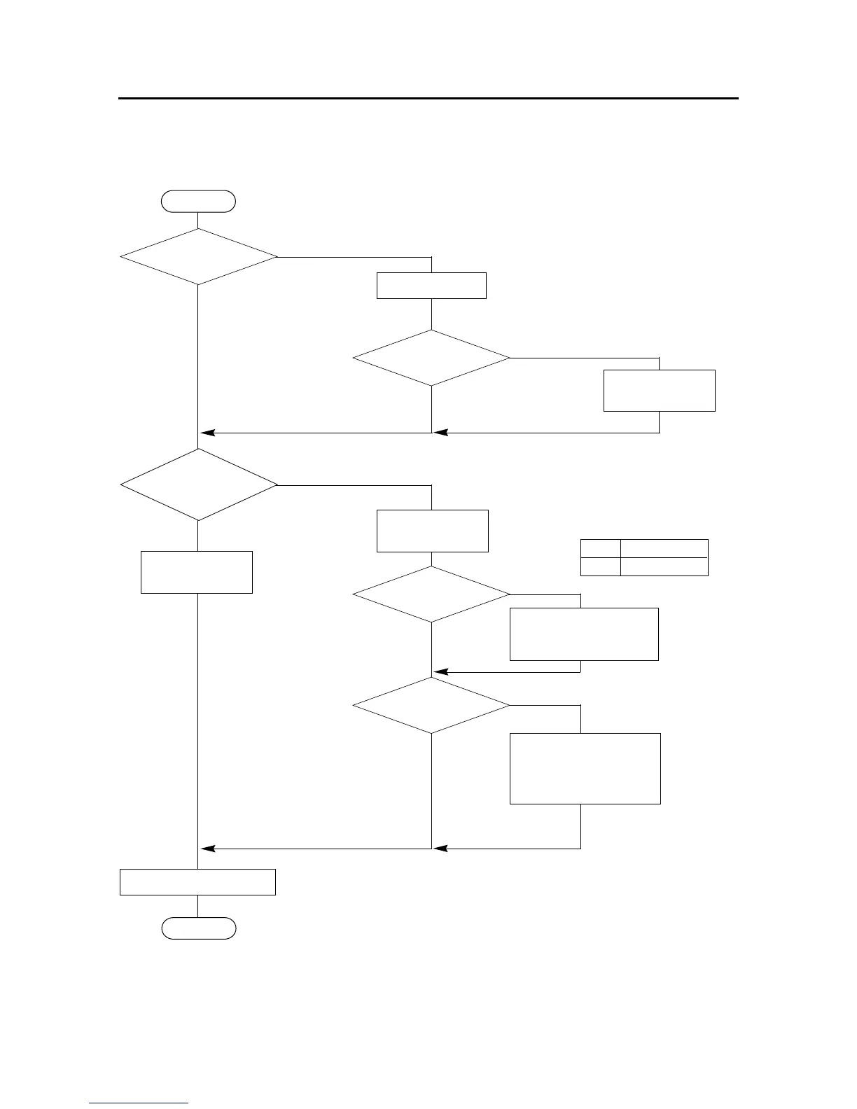
A flowchart detailing the unit replacement process.
Flowcharts for diagnosing and replacing specific faulty parts.
Explains the structure and conventions of the parts list.
Detailed diagrams and lists for printer assembly and mechanism components.
Illustrations and parts for sub-assemblies like case, interface, and frame units.
Circuit diagrams, component layouts, and parts lists for logic and control boards.
Schematics and component lists for parallel and serial interface boards.
Oscilloscope waveforms illustrating printer signal operations.