EasyManua.ls Logo

Star Micronics TUP500 series User Manual

Star Micronics TUP500 series
127 pages
To Next Page IconTo Next Page
To Previous Page IconTo Previous Page
Page #61 background imageLoading...
Page #61 background image
TUP500 Series Product Specifications
8-13
8.3. Fastening the Friction Spring
It is necessary to adjust the friction spring position for the width of the paper you intend to use. If the setting posi-
tion is incorrect, the roll paper will be supplied improperly to the mechanism which in turn causes paper transport
problems. Thus, it is should be properly adjusted.
Notes:
1. After adjusting the position, slowly turn the roll paper to check that it turns smoothly.
2. It is necessary to make fine adjustments to the friction spring position according to the
roll paper material.
Contact us for details on fine adjustments.
8.3.1. Using the Spring Base
The scale of the spring holder shown in Fig. 8.3.1.A. is a 2 mm pitch. Adjust or mount the friction spring width of
the paper you intend to use. The following shows the representative paper width settings.
Notes:
1. Fit the friction spring between the top and bottom guide rail on the spring base to fasten
the friction spring. At this time, be careful that the friction spring is not riding up on the
guide rail when fastened.
Fig. 8.3.1.A
Scale d
Scale d
Scale c’
Scale b’
Scale c
Scale b
Scale a
Scale a
1 (Pitch)
1 (Pitch)

Table of Contents

Question and Answer IconNeed help?

Do you have a question about the Star Micronics TUP500 series and is the answer not in the manual?

Star Micronics TUP500 series Specifications

General IconGeneral
BrandStar Micronics
ModelTUP500 series
CategoryPrinter
LanguageEnglish

Summary

1. GENERAL DESCRIPTION

How to Display the Model Name

Explains how to interpret the TUP500 model name structure.

2. CONFIGURATION

2.1. Basic Configuration and Descriptions of Modules

Describes the modular composition of the TUP500 printer.

2.2. Optional Parts Selectable for the Modules

Lists selectable options for printer modules.

3. BASIC SPECIFICATIONS

3.1. Print Specifications

Details printing method, dot configuration, density, and region.

3.2. Character Specifications and Bar Code Specifications

Details character and barcode specifications for STAR Line Mode.

3.3. Paper Specifications

Covers paper width, thickness, and external diameter specifications.

3.4. Thermal Mechanism Module

Details thermal head configuration, density, and voltage.

3.5. Presenter Module

Details presenter conveyance roller feed method and speed.

3.6. Roll Paper Supply Module

Details roll paper support, width adjustment, and paper tube specs.

3.7. Reliability Specifications

Covers mechanical, thermal head, and auto-cutter reliability.

4. EXTERNAL SPECIFICATIONS

4.1. External Specifications

Details external dimensions of printer units.

4.2. Operating Unit Specifications

Explains the function of the power and feed/cancel switches.

5. AMBIENT SPECIFICATIONS

5.1. Temperature and Humidity

Details operating and storage temperature/humidity ranges.

5.2. EMC (Electromagnet Compatibility)

Lists emission standards and limit values.

5.3. Vibration/Falling Shocks

Specifies vibration test conditions.

6. RELATED RULES

6.1. Compatible Specifications

Lists country-specific compatible standards.

7. USAGE EXAMPLE (LAYOUT EXAMPLE)

7.2. Layout of the Large Roll Paper Holder Unit (RUH-T500, Optional)

Explains layout considerations for the optional paper holder.

8. PRINTER SETUP

8.1. Mounting the Units

Instructions for mounting the printer and optional units.

8.3. Fastening the Friction Spring

Instructions for fastening friction spring.

8.4. Adjusting the Near-end Sensor Unit

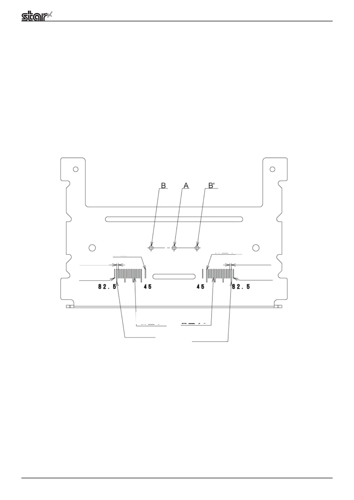
Method for adjusting sensor position for paper width.

9. HANDLING THE PRINTER UNIT

9.1. How to Set the Roll Paper

Step-by-step guide for loading roll paper.

9.2. Maintenance Method

Instructions for periodic cleaning of thermal mechanism and presenter.

9.4. Precautions for Handling

Important safety and handling precautions for the printer.

9.5. Precautions Concerning Safety

General safety precautions for printer operation and maintenance.

10. CIRCUIT GENERAL SPECIFICATIONS

10.1. General Specifications

Overview of interface, power, dimensions, and board components.

11. CIRCUIT CONFIGURATION

11.1. Block Diagram

Visual representation of the printer's circuit connections.

12. CIRCUIT CONNECTION SPECIFICATIONS

12.1. Connector Specifications and Signal Names

Details connectors and their signal assignments on the control PCB.

13. DIP SWITCH SPECIFICATIONS

13.1. Main Board DIPSW 1

Details DIP switch settings for various interfaces.

14. MSW SPECIFICATIONS

14.1. MSW 0

Specifies memory switch settings for destination and character modes.

14.2. MSW1

Specifies memory switch settings for top margin, fonts, and international characters.

14.3. MSW2

Specifies memory switch settings for print speed and density.

14.4. MSW3

Specifies memory switch settings for code pages and character positions.

14.5. MSW4

Specifies memory switch settings for print mode and region.

14.6. MSW5

Specifies memory switch settings for presenter auto-recovery and snout control.

14.7. MSW6

Specifies memory switch settings for auto-loading and presenter paper position.

14.8. MSW 7

Specifies memory switch settings for ASB functions.

14.9. MSW8

Specifies memory switch settings for loaded format on power-on.

14.11. MSWA

Specifies memory switch settings for NE sensor input.

15. OPERATING SPECIFICATIONS

15.1. Operating Specifications

Overview of printer operations via switches and LEDs.

15.2. LED Specifications

Details the meaning and behavior of system LEDs.

15.3. Error Specifications

Describes auto-recovery errors and their cancellation.

15.4. Sensor Adjustment Mode Specifications

Procedure to adjust PE/Black Mark sensor sensitivity.

16. COMMAND SPECIFICATIONS AND CHARACTER CODES

16.1. STAR Line Mode

Refers to separate document for STAR Line Mode command specs.

Related product manuals