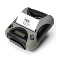
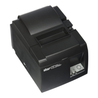
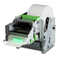
TUP500 Series Product Specifications
13-1
13. DIP SWITCH SPECIFICATIONS
DIP switches are loaded when the power is turned on or when the printer is reset. Therefore, when you change the
settings, enable them by turning the printer on again, or by executing a printer reset. Turn the power off before changing
the PCB and interface type.
13.1. Main Board DIPSW 1
1) Parallel I/F
DIPSW1 Function ON OFF
DIPSW1-1 Emulation (*1) (See table below)
DIPSW1-2
DIPSW1-3 (Reserved) --- ---
DIPSW1-4 Sensor Adjustment Mode Invalid Valid
DIPSW1-5 Reset by INIT Signal Valid Invalid
DIPSW1-6 BUSY Condition Reception Buffer Full/OFF-LINE Reception Buffer Full
DIPSW1-7 (Reserved) --- ---
DIPSW1-8 NE Sensor Contact State (*3) Non-contact Contact
DIPSW1-9 Low Peak Current Mode Invalid Valid
DIPSW1-10 (Reserved) --- ---
2) RS232 I/F (25pin/9Pin)
DIPSW1 Function ON OFF
DIPSW1-1 Emulation (*1) (See table below)
DIPSW1-2 (See table below)
DIPSW1-3 (Reserved) --- ---
DIPSW1-4 Sensor Adjustment Mode Invalid Valid
DIPSW1-5 (Reserved) --- ---
DIPSW1-6 BUSY Condition Reception Buffer Full/OFF-LINE Reception Buffer Full
DIPSW1-7 (Reserved) --- ---
DIPSW1-8 NE Sensor Contact State (*3) Non-contact Contact
DIPSW1-9 Low Peak Current Mode Invalid Valid
DIPSW1-10 (Reserved) --- ---
3) USB I/F
DIPSW1 Function ON OFF
DIPSW1-1 Emulation (*1) (See table below)
DIPSW1-2 (See table below)
DIPSW1-3 (Reserved) --- ---
DIPSW1-4 Sensor Adjustment Mode Invalid Valid
DIPSW1-5 USB Mode Printer Class Vendor Class
DIPSW1-6 BUSY Condition Reception Buffer Full/OFF-LINE Reception Buffer Full
DIPSW1-7 (Reserved) --- ---
DIPSW1-8 NE Sensor Contact State (*3) Non-contact Contact
DIPSW1-9 Low Peak Current Mode Invalid Valid
DIPSW1-10 (Reserved) --- ---
 Loading...
