Engine Electrical Devices: 1C-11
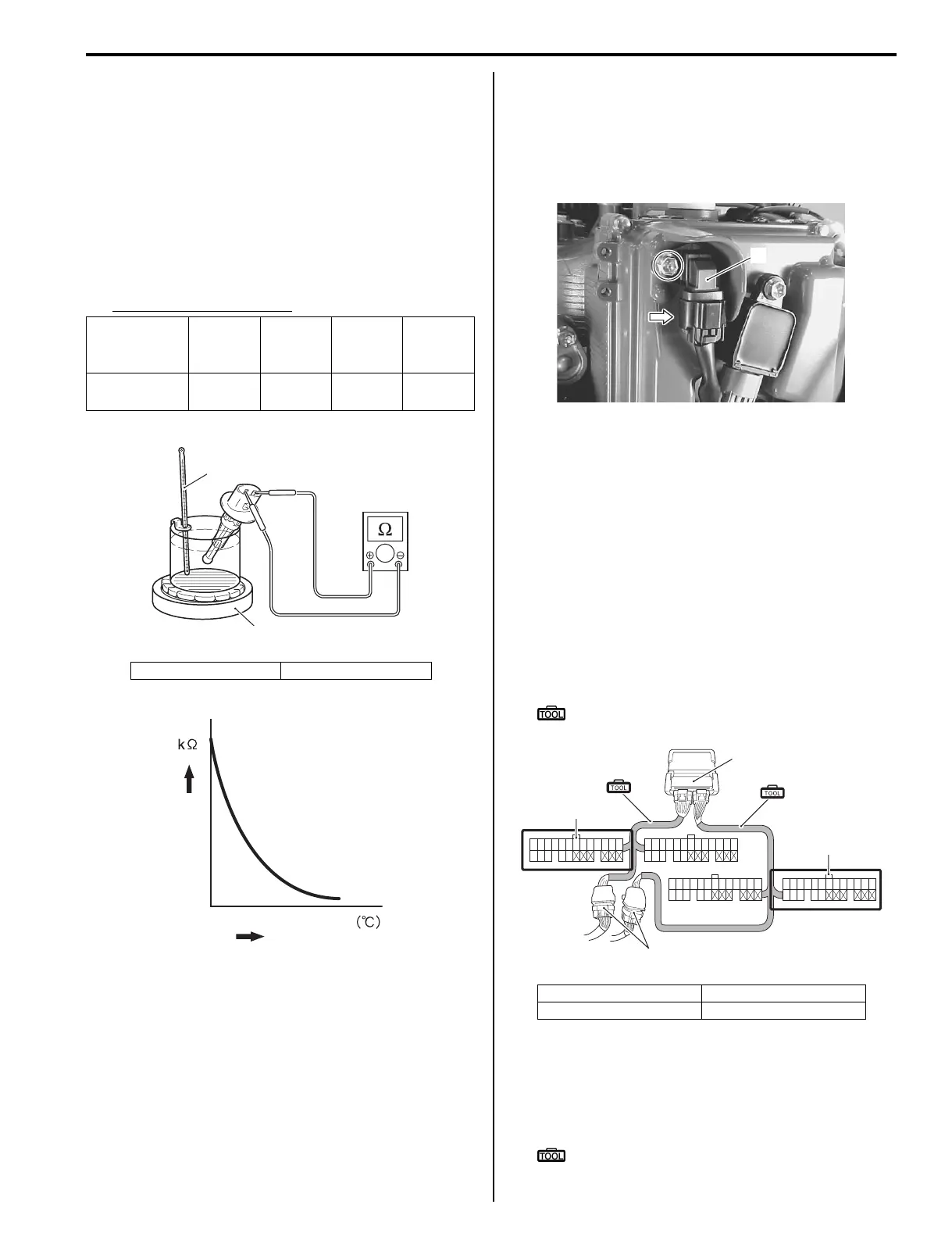
IAT Sensor Inspection
Z9J0111306009
1) Remove the IAT sensor.
Refer to “IAT Sensor Removal and Installation”
(Page 1C-10).
2) Immerse temperature sensing part of IAT sensor in
water.
3) Measure resistance between sensor terminals while
heating water gradually.
4) If measured resistance does not change in the
proportion indicated, replace sensor.
IAT sensor specification
5) Reinstall the IAT sensor.
Refer to “IAT Sensor Removal and Installation”
(Page 1C-10).
CMP Sensor Removal and Installation
Z9J0111306010
Removal
1) Disconnect the CMP sensor lead wire connector at
sensor.
2) Remove the bolt and CMP sensor (1).
Installation
Installation is reverse order of removal.
• Install CMP sensor, then tighten mounting screw
securely.
• Connect sensor lead wire connector to CMP sensor.
CMP Sensor Inspection
Z9J0111306011
1) Turn ignition switch OFF.
2) Remove the bolt and CMP sensor.
3) Connect the 36-pin test cord set between ECM and
wire harness as shown in figure.
Special tool
(A): 09930–88730 (36-pin test cord set)
4) Connect the tester probe (“+”, Red) to No. 40
terminal.
5) Connect the tester probe (“–”, Black) to No. 25
terminal (or to body ground).
Special tool
: 09930–99320 (Digital tester)
Water
temperature:
°C (°F)
0 (32) 25 (77) 50 (122) 75 (135)
Resistance
(kΩ)
5.3 – 6.6 1.8 – 2.3
0.73 –
0.96
0.33 –
0.45
1. Thermometer 2. Heater
1
2
I9J011130007-03
Temperature
Resistance
I9J011130008-02
1. Wire harness 3. Black connector
2. White connector
1
I9J011130046-01
37
50
38
51
39
52
40 41
53 54
42 43 44 45 46 47 48 49 55
68
56
69
57
70
58 59
71
60 61 62 63 64 65 66 67
19 20 21 22 23 24 25 26 27 28 29 30 3112345678910111213
14 15 16 17 18
32 33 34 35 36
72
ECM
(A)
(A)
2
3
1
I9J011130052-02

 Loading...


