Engine Electrical Devices: 1C-1
Power Head
Engine Electrical Devices
Precautions
Precaution for Engine Electrical Device
Z9J0111300001
Refer to “General Precautions” in Section 00 (Page 00-1) and “Precautions on Engine Diagnosis” in Section 1A
(Page 1A-1).
General Description
Sensor and Switch Description
Z9J0111301001
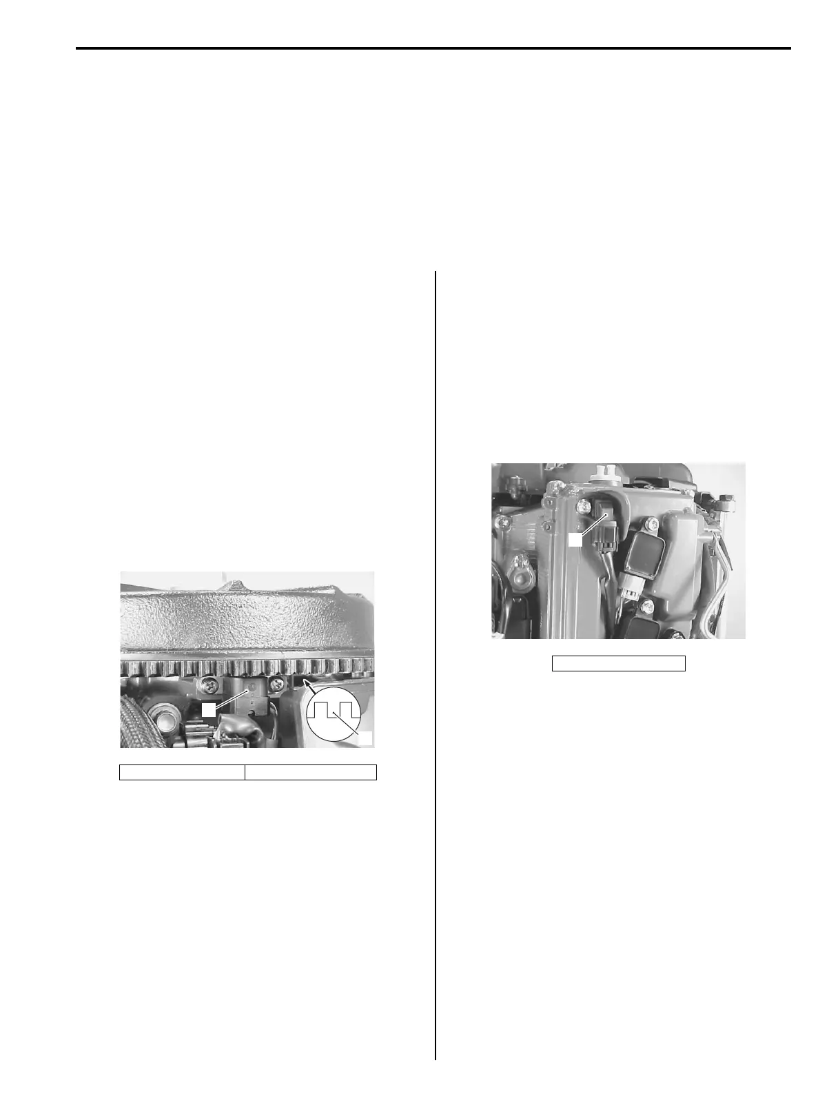
CKP Sensor
• There is one CKP sensor installed below the flywheel
rotor.
When the reluctor bars on the flywheel pass the
sensor, a signal (voltage pulse) is generated and sent
to the ECM. This is the fundamental signal used to
judge engine speed and crankshaft angle.
• There are 32 reluctor bars. They are located 10
degrees apart, except at two positions where they are
30 degrees apart.
During one crankshaft rotation, 32 signals are input to
the ECM.
• Failure symptom:
Without the CKP sensor signal input, the ECM does
not output the ignition and fuel injection signals.
CMP Sensor
• The CMP sensor is mounted on the cylinder head
cover and the trigger vanes are pressed onto the end
of the exhaust camshaft.
This sensor is used to detect piston position.
• Signals received from this sensor are also used by the
ECM to determine sequential fuel injection and
ignition control.
• The 12 V power to the CMP sensor is supplied
through the Ign (Gr) line of the ignition switch.
1. CKP sensor 2. Reluctor bar
1
2
I9J011130026-01
1. CMP sensor
1
I9J011130027-01

 Loading...


