1C-2 Engine Electrical Devices:
• The CMP sensor is a GMR (Giant Magnet Resistive)
semiconductor type sensor.
The GMR semiconductor has the property of varying
the electrical resistance depending on the intensity of
the magnetic force applied.
When the line of magnetic force from the magnet to
the GMR semiconductor is increased or decreased,
the electrical resistance of the GMR semiconductor
will change. The changes in resistance as the
magnets pass create the sensors waveform.
When a trigger vane on the camshaft reluctor aligns
with the sensors internal magnet, the electrical
resistance of the GMR will decrease.
When a trigger vane moves away from the sensor, the
electrical resistance of the GMR will increase.
When the GMR semiconductor voltage becomes
higher than the standard value, the sensors signal will
be lower. And when the voltage becomes lower than
the standard value, the sensors signal will be higher.
The six camshaft trigger vanes provide six high
voltage signals from the CMP sensor to the ECM
during one camshaft rotation (two rotations of
crankshaft).
• Failure symptom:
Without the CMP sensor signal input, the ECM does
not output the ignition and fuel injection signals.
• ECM cylinder identification:
The cylinders are identified by a calculation of two
signals; one from the CKP sensor and one from the
CMP sensor.
The ECM measures the time interval of the signals
inputted from the CKP sensor.
When the ECM detects a signal interval that is longer
than normal, it determines that the wide space
between the reluctor bars (30 degree spaced apart
section) has passed through the CKP sensor.
The ECM identifies the cylinder by the number of
CMP sensor signal inputs and the input timing
(pattern) within the gap of the widely spaced reluctors
that have passed the CKP sensor. There are 2 CMP
sensor signal inputs to the ECM when the #1 or #4
cylinders are on the compression stroke, but the input
timing (pattern) is different.
Thus the cylinder identification is established.
When a compression stroke takes place either in the
#2 or the #3 cylinder, the number of CMP sensor
signal inputs is 1. Likewise, the cylinder identification
is established by the CMP sensor input timing
(pattern).
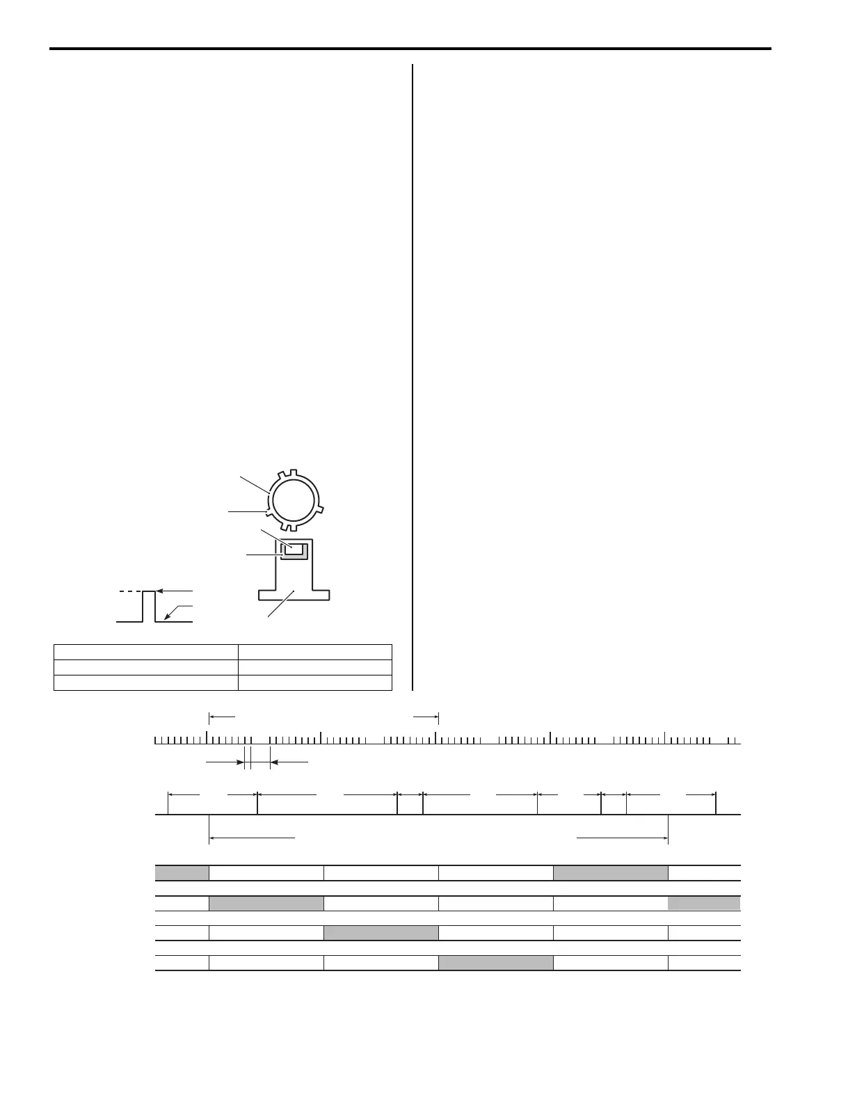
1. Camshaft 4. Magnet
2. Trigger vane 5. CMP sensor
3. Magnet resistive semiconductor
Signal
High
Low
1
2
3
5
4
I9J011130001-01
No.1 cylinder
No.3 cylinder
No.4 cylinder
No.2 cylinder
CKP sensor
signal
CMP sensor
signal
In.
Ex.
Ep.
Cm.
In.
Ex.
Ep.
Cm.
In.
Ex.
Ep.
Cm.
In.
Ex.
Ep.
Cm.
In.
Ex.
Ep.
Cm.
In.
Ex.
Ep.
Cm.
140°
40°
180°
100°
40°
140°
CMP sensor - 6 signals / 720° (crankshaft 2 rotation)
Cm.: Compression, Ep.: Explosion, Ex.: Exhaust, In.: Intake
32 signals / crankshaft 1 rotation
TDC
TDC
TDC
TDC
TDC
TDC
TDC
TDC
220°
10° 30°
I9J011130002-04

 Loading...


