Housing and Bracket: 2A-3
Lower Side Cover Removal and Installation
Z9J0112106002
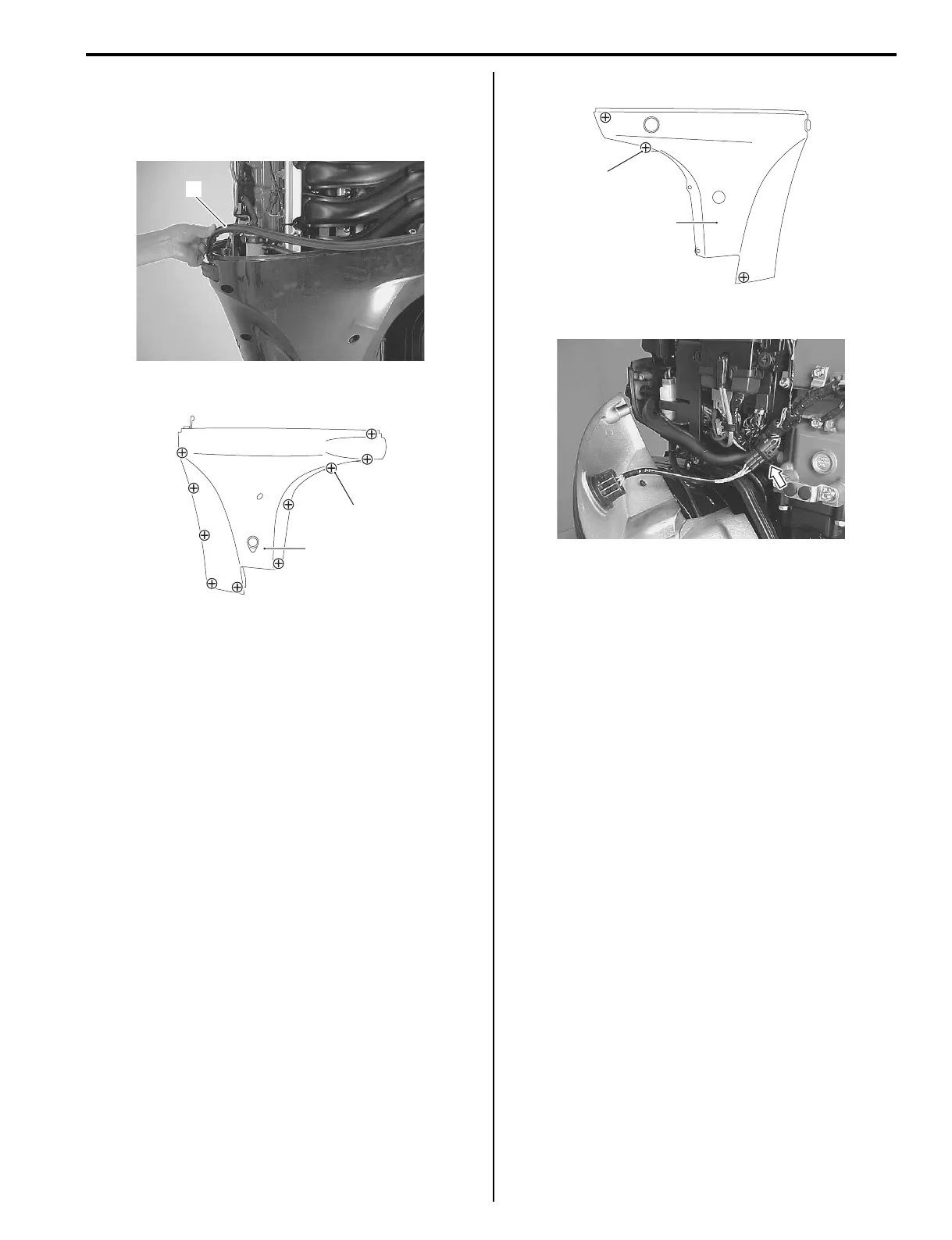
Removal
1) Remove the side cover rubber (1).
2) Remove ten screws (2) and STBD side cover (3).
3) Remove three screws (4) and PORT side cover (5).
4) Disconnect PTT switch lead connector.
Installation
Installation is reverse order of removal with special
attention to the following step.
• Tighten side cover screws, pre-coated with thread
lock, to specified torque.
Tightening torque
Side cover screw: 7 N·m (0.7 kgf-m, 5 lbf-ft)
1
I9J011210009-01
2
3
I9J011210007-02
4
5
I9J011210008-02
I9J011210010-01

 Loading...


